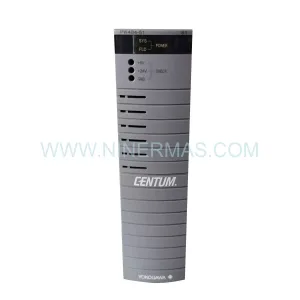
Original Industrial Spare Part
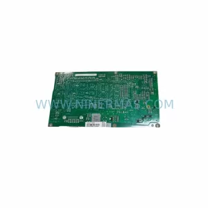
Schneider TSXSUP702 Retrofit-Compatible Power Supply for Legacy Systems
Verify the part, confirm the platform family, and move straight into quotation with the right commercial details.
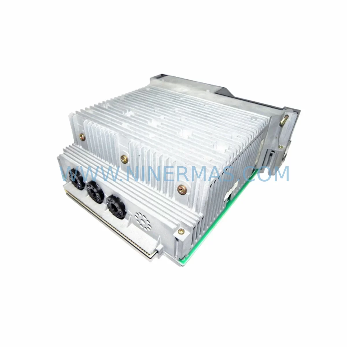
RFQ Ready
- SKUTSXSUP702 TSX7
- CategoryPLC & Industrial Automation Modules
- BrandSchneider Electric
- SupportAvailability, lead time, condition, and shipping coordination
How Buyers Usually Use This Page
- Confirm the exact part number and platform family before sending the quote request.
- Use direct email when quantity, condition, and destination are already defined internally.
- Switch to the broader brand or category archive when you need alternates nearby.
Series Navigation
Move through the most common platform families behind this part.
Product RFQ
Send this part directly for quotation.
Include quantity, required condition, destination country, and target delivery timing. Current reference: Schneider TSXSUP702 Retrofit-Compatible Power Supply for Legacy Systems with SKU TSXSUP702 TSX7.
Schneider TSXSUP702 Retrofit-Compatible Power Supply for Legacy Systems
The Schneider Electric TSXSUP702 is a rack-mounted DC power supply module designed for the TSX7 series programmable logic controller platform — one of Schneider’s most widely deployed legacy automation architectures across process industries, discrete manufacturing, and infrastructure control. As the TSX7 platform has reached end-of-life and original spare parts become increasingly scarce, the TSXSUP702 remains a critical component for engineers managing retrofit projects, system life extension programs, and unplanned downtime recovery on existing production lines.
This unit is sourced, inspected, and pre-shipment tested to confirm output voltage stability, inrush current behavior, and backplane power delivery before dispatch. Each unit ships with a 12-month warranty, providing procurement teams and maintenance engineers with the confidence needed for long-cycle spare parts planning.
Upgrade Compatibility Table
| Parameter | TSXSUP702 Specification | Retrofit / Replacement Notes |
|---|---|---|
| Series Compatibility | TSX7 rack platform | Verify rack slot position; not cross-compatible with TSX Micro or TSX Premium racks |
| Input Voltage | 100–240 VAC, 50/60 Hz | Confirm site supply voltage and UPS output before installation |
| Output | +5 VDC / +24 VDC backplane rails | Measure existing rail voltages before swap to confirm baseline |
| Rack Interface | TSX7 backplane connector (proprietary) | Inspect backplane pins for corrosion or mechanical damage prior to seating |
| Module Slot | Dedicated PSU slot (slot 0) | No address configuration required; slot-defined power role |
| Communication Impact | None (passive power role) | CPU, TSXP57 processor, and I/O modules retain program memory during hot-swap if UPS is active |
| Installation Space | Standard TSX7 rack width module | Confirm rack has no physical obstruction in slot 0; check DIN rail clearance |
| Commissioning | No software configuration required | Power-on self-test via LED indicators; verify +5V and +24V rails with multimeter post-installation |
| Warranty | 12-Month Warranty — covers manufacturing defects and output failure under normal operating conditions | |
Retrofit Planning for Existing Automation Systems
When planning a TSXSUP702 replacement within an active TSX7-based control system, the scope of work extends well beyond the power supply module itself. A structured retrofit assessment should begin with a full audit of the existing rack configuration. In a typical TSX7 installation, the rack may house a TSXP57 CPU module alongside discrete and analog I/O modules such as the TSXDEY16D2 (16-channel digital input) or TSXAEY414 (analog input module). Each of these modules draws power from the backplane rails supplied by the TSXSUP702, making power budget verification a mandatory first step before any swap is attempted.
Terminal wiring on the field side must be documented before shutdown. Engineers should photograph or export the existing wiring schedule from the TSXPCX1031 programming cable connection to the PL7 Pro or Unity Pro programming environment, capturing the current I/O mapping, symbol table, and program version. This ensures that if a module address conflict arises after the power supply replacement, the original logic can be restored without ambiguity.
For sites running Uni-Telway or Modbus serial communication through a TSXSCP111 or TSXSCP114 communication module seated in the same rack, the communication link to upstream SCADA or HMI systems — often a Magelis XBTGT series panel — must be verified to remain stable after the power cycle. Serial communication parameters (baud rate, parity, station address) should be recorded and confirmed post-restart.
Where the TSX7 rack interfaces with remote I/O drops via Fipio or Fipway fieldbus, the bus master configuration held in the CPU must be preserved. A cold restart following a power supply swap will re-initialize the fieldbus scan cycle; engineers should confirm that all remote TSXETY110 or TSXFPP20 fieldbus interface modules reconnect within the expected timeout window before releasing the line to production.
In control cabinets where space is constrained, the physical removal of the TSXSUP702 requires careful handling of adjacent modules. If a TSXRKY8EX rack extension is present, the inter-rack cable must be disconnected in the correct sequence to avoid backplane fault signals being latched in the CPU. Signal isolators installed on analog loops — particularly on thermocouple or 4–20 mA process inputs — should be checked for drift after the power restoration, as brief supply interruptions can affect zero-calibration on older isolation barriers.
Finally, for sites where the TSX7 system is being partially migrated toward a Modicon M340 or Modicon M580 platform, the TSXSUP702 replacement may serve as an interim measure while the full migration is planned. In this scenario, maintaining a tested spare TSXSUP702 in stock provides a critical buffer against unplanned downtime during the transition period, allowing the legacy system to remain operational while new rack hardware, BMXXBP0800 backplanes, and BMEP582040 processors are commissioned in parallel.
Downtime Control During System Migration
Minimizing production downtime during a TSXSUP702 replacement requires a disciplined pre-outage preparation protocol. The most effective approach is to schedule the swap during a planned maintenance window and prepare a fully tested replacement unit in advance — confirmed operational via bench power-on test before the maintenance window begins.
Before initiating the shutdown, the current PLC program should be uploaded and saved from the TSXPCX1031 or equivalent programming cable connection using PL7 Pro, with the project file archived to a secure location. This protects against the unlikely event of CPU memory loss during the power interruption. If the site operates with a UPS on the control cabinet, the UPS should be confirmed capable of sustaining the CPU and critical I/O modules for the duration of the swap — typically 5 to 15 minutes for an experienced technician performing a like-for-like module replacement.
Post-installation, the commissioning sequence should follow a structured power-up: apply AC input, observe the TSXSUP702 status LEDs for normal indication, then verify backplane rail voltages at the rack test points before allowing the CPU to enter RUN mode. Any fieldbus or serial communication links should be confirmed re-established before HMI operator screens are released from maintenance mode. Documenting the as-found and as-left conditions — including rail voltages, LED states, and communication link status — provides a traceable record for maintenance management systems and supports future lifecycle planning for the remaining TSX7 hardware.
Retrofit Support FAQ
Q1: Is the TSXSUP702 a direct drop-in replacement for the original Schneider TSX7 power supply?
Yes. The TSXSUP702 is designed specifically for the TSX7 rack platform and occupies the dedicated slot 0 position. No address configuration or software changes are required. Verify the rack model and slot condition before installation.
Q2: What pre-shipment testing is performed on each unit?
Each TSXSUP702 unit undergoes output voltage verification on both the +5 VDC and +24 VDC rails, inrush current observation, and visual inspection of the backplane connector and housing before dispatch. A test record is available on request.
Q3: Can this unit be used during a partial migration to Modicon M340 or M580?
Yes. The TSXSUP702 is suitable as an interim spare to keep the legacy TSX7 rack operational while a phased migration to newer Modicon platforms is underway. It provides a cost-effective bridge solution that avoids forced full-system replacement under time pressure.
Q4: What is covered under the 12-month warranty?
The 12-month warranty covers manufacturing defects and output failure under normal operating conditions, including backplane power delivery faults attributable to the module. Physical damage caused by incorrect installation, overvoltage events, or environmental contamination is excluded. Contact our team for warranty claims or technical support.
| Product Series | TSX |
|---|---|
| Country of Origin | FR |
Catalog Continuation
More Schneider Electric modules in the catalog.
Use the brand lane to compare nearby part numbers, platform-adjacent modules, and other inquiry-ready listings before sending your final RFQ.
Catalog Continuation
Alternative parts within PLC & Industrial Automation Modules.
Stay inside the same system family when you need substitutes, adjacent modules, or a broader shortlist for procurement review.
SKU: 6FC5357-0BB12-0AE0
Siemens 6FC5357-0BB12-0AE0 Service-Ready Industrial Spare Part
SKU: 3BSE011790R1(PXHK401)
ABB 3BSE011790R1 PXHK401 Retrofit-Ready Communication Module