Original Industrial Spare Part
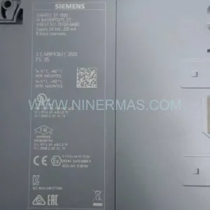
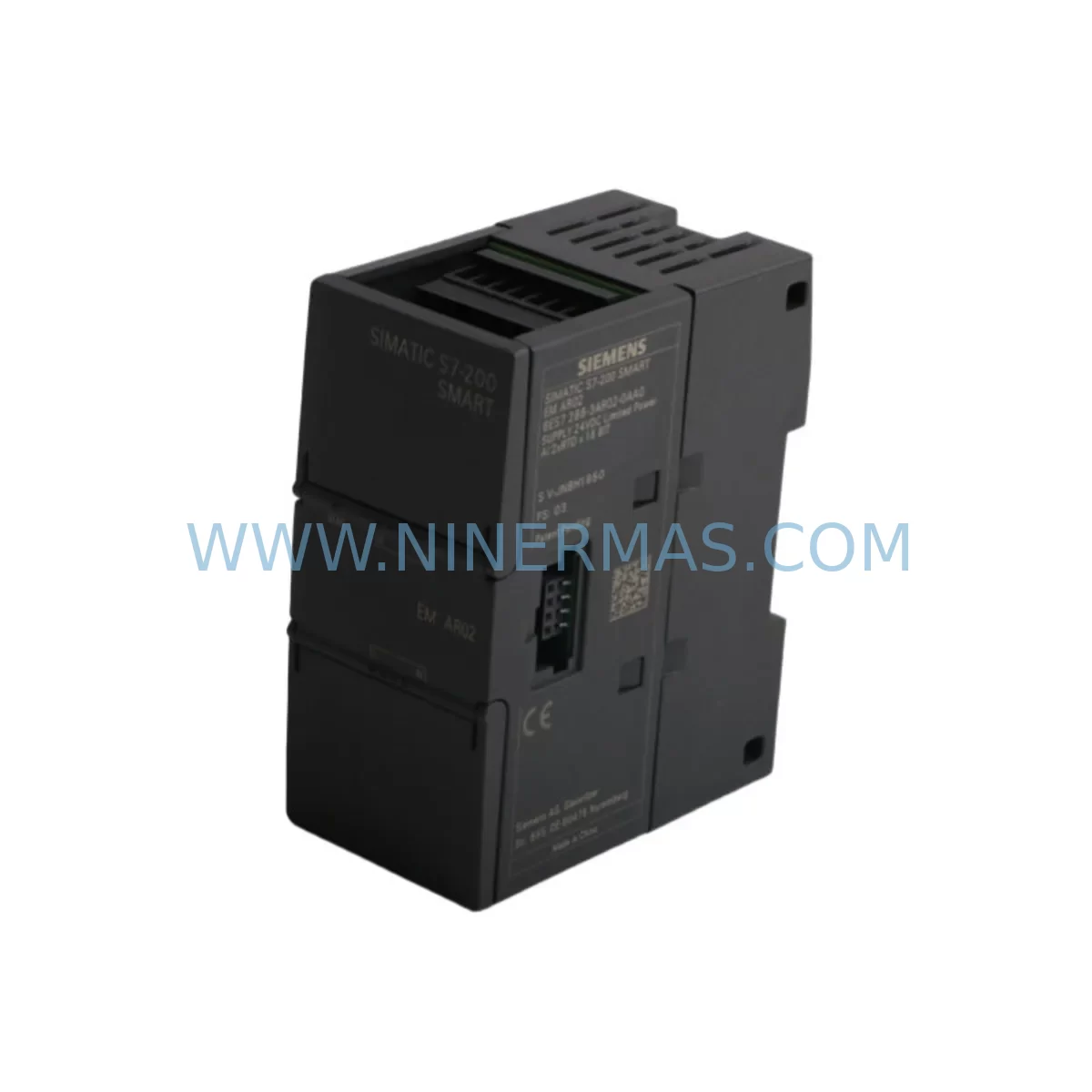
Siemens 6ES7288-3AR02-0AA0 RTD Analog Input Module
Verify the part, confirm the platform family, and move straight into quotation with the right commercial details.
RFQ Ready
- SKU6ES7288-3AR02-0AA0
- CategoryPLC & Industrial Automation Modules
- BrandSiemens
- SupportAvailability, lead time, condition, and shipping coordination
How Buyers Usually Use This Page
- Confirm the exact part number and platform family before sending the quote request.
- Use direct email when quantity, condition, and destination are already defined internally.
- Switch to the broader brand or category archive when you need alternates nearby.
Series Navigation
Move through the most common platform families behind this part.
Product RFQ
Send this part directly for quotation.
Include quantity, required condition, destination country, and target delivery timing. Current reference: Siemens 6ES7288-3AR02-0AA0 RTD Analog Input Module with SKU 6ES7288-3AR02-0AA0.
Siemens 6ES7288-3AR02-0AA0 RTD Analog Input Module: Retrofit-Compatible Upgrade for Legacy Control Systems
The Siemens 6ES7288-3AR02-0AA0 is a dedicated RTD (Resistance Temperature Detector) analog input expansion module designed for the S7-200 SMART series programmable logic controller platform. This module supports PT100, PT1000, Ni100, Ni1000, and resistance-type sensors, making it a precision temperature acquisition solution for industrial process control, HVAC automation, boiler management, and legacy system modernization projects. For maintenance engineers managing aging S7-200 or S7-200 CN installations, the 6ES7288-3AR02-0AA0 provides a direct, retrofit-compatible upgrade path that preserves existing wiring infrastructure and minimizes engineering rework.
As original S7-200 CPU modules such as the CPU 224XP and CPU 226 approach end-of-life and spare parts availability tightens, plant operators increasingly rely on the S7-200 SMART platform as the preferred migration target. The 6ES7288-3AR02-0AA0 slots directly into the S7-200 SMART expansion bus, connecting via the local I/O ribbon cable to compatible CPUs including the CPU SR20, CPU SR30, CPU SR40, CPU ST40, and CPU ST60. This plug-and-play compatibility eliminates the need for additional signal conditioning hardware in most retrofit scenarios, reducing both installation time and total project cost.
When planning a retrofit from an older S7-200 analog input module such as the EM 231 RTD or EM 235, engineers must verify several critical parameters before commissioning. Power budget confirmation is the first step: the S7-200 SMART CPU provides a fixed 5 VDC bus supply to expansion modules, and the total current draw across all connected expansion modules — including analog output modules like the 6ES7288-3AQ02-0AA0, digital I/O modules such as the 6ES7288-2DR08-0AA0, and the RTD module itself — must not exceed the CPU’s rated expansion current capacity. Exceeding this limit requires the addition of an external 24 VDC power supply module to supplement the bus.
Terminal wiring adaptation is the second critical checkpoint. The 6ES7288-3AR02-0AA0 uses a removable screw-terminal connector block, supporting 2-wire, 3-wire, and 4-wire RTD configurations. When migrating from legacy EM 231 RTD wiring, technicians should confirm sensor wire gauge compatibility and re-verify shielding continuity, particularly in environments with high electromagnetic interference from variable frequency drives (VFDs) or servo amplifiers. Proper cable shielding grounded at a single point prevents common-mode noise from corrupting temperature readings.
Backplane interface and module address assignment must also be confirmed during retrofit planning. The S7-200 SMART system assigns I/O addresses sequentially based on module slot position in the expansion chain. If the 6ES7288-3AR02-0AA0 replaces a module of a different type or is inserted at a different slot position than the original analog module, the corresponding AIW (Analog Input Word) addresses in the STEP 7-Micro/WIN SMART program must be updated accordingly. Failure to realign address mapping will result in incorrect temperature readings or program faults at startup.
Program compatibility review is essential before going live. The STEP 7-Micro/WIN SMART programming environment provides a hardware configuration wizard that auto-detects connected expansion modules and validates address assignments. Engineers should export the existing program, review all analog input instructions referencing AIW addresses, and confirm that scaling blocks — typically implemented using the SCALE or linear interpolation instructions — correctly map raw RTD counts to engineering units (°C or °F). If the legacy program was developed in STEP 7-Micro/WIN for the original S7-200, a migration utility is available to assist with instruction set translation.
HMI screen updates are frequently overlooked during RTD module replacements. If the plant uses a SIMATIC HMI panel such as the KTP700 Basic or TP1200 Comfort connected via Ethernet or RS-485 to the S7-200 SMART CPU, temperature display tags linked to the old AIW addresses must be remapped in WinCC flexible or TIA Portal to reflect the new address assignments. Skipping this step results in HMI screens displaying frozen or incorrect temperature values even after the PLC program is running correctly.
Communication link integrity should be verified after module installation. The S7-200 SMART CPU supports Ethernet (via the onboard RJ45 port) and RS-485 (via Port 0) for SCADA connectivity. If the plant SCADA system — such as WinCC, iFIX, or a third-party OPC server — polls temperature data from the CPU, the OPC tag database should be audited to confirm that all temperature-related tags correctly reference the updated AIW addresses. A brief online monitoring session using STEP 7-Micro/WIN SMART’s status chart function can confirm live data flow before handing over to operations.
Installation space confirmation is a practical concern in dense control cabinet retrofits. The 6ES7288-3AR02-0AA0 has a compact form factor consistent with the S7-200 SMART expansion module family, but engineers should verify available DIN rail space and cable routing clearance, particularly when the cabinet also houses a 6ES7288-1SR20-0AA0 or 6ES7288-1SR30-0AA0 CPU module alongside multiple expansion modules, a 24 VDC SITOP power supply, and communication modules such as the CM01 RS-485/RS-232 signal board.
On-site commissioning should follow a structured sequence: power-on self-test confirmation, module recognition in STEP 7-Micro/WIN SMART hardware configuration, live RTD sensor reading verification against a calibrated reference thermometer, and alarm threshold validation in both the PLC program and the SCADA system. Documenting as-built wiring changes and updated address maps in the plant maintenance records ensures that future maintenance personnel can service the system without reverse-engineering the retrofit modifications.
All units supplied by NINERMAS are sourced from authorized distribution channels and undergo pre-shipment functional verification. Each 6ES7288-3AR02-0AA0 is covered by a 12-month warranty against manufacturing defects, with stock available for immediate dispatch to support urgent maintenance and unplanned downtime recovery scenarios.
Upgrade Compatibility Table
| Parameter | Legacy: EM 231 RTD (S7-200) | Replacement: 6ES7288-3AR02-0AA0 (S7-200 SMART) |
|---|---|---|
| Compatible CPU Platform | S7-200 CPU 224, 226 | S7-200 SMART CPU SR/ST Series |
| RTD Input Channels | 2 channels | 2 channels |
| Supported Sensor Types | PT100, Ni100 | PT100, PT1000, Ni100, Ni1000, Resistance |
| Wiring Configuration | 2-wire / 3-wire | 2-wire / 3-wire / 4-wire |
| Bus Interface | S7-200 expansion ribbon cable | S7-200 SMART expansion ribbon cable |
| Address Assignment | Fixed AIW per slot position | Sequential AIW per slot position (STEP 7-Micro/WIN SMART) |
| Communication Protocol | PPI / MPI via CPU | Ethernet / RS-485 via CPU |
| Installation Format | DIN rail, snap-on | DIN rail, snap-on |
| Programming Environment | STEP 7-Micro/WIN | STEP 7-Micro/WIN SMART |
| Retrofit Recommendation | Direct slot replacement with AIW address remapping required | |
| Commissioning Focus | Sensor wiring verification, address mapping, HMI tag update, SCADA OPC audit | |
| Warranty | — | 12-Month Warranty (NINERMAS) |
Retrofit Planning for Existing Automation Systems
A successful retrofit centered on the 6ES7288-3AR02-0AA0 typically involves coordinating multiple components across the control cabinet. The S7-200 SMART CPU — whether a CPU SR20, CPU SR30, or CPU ST40 — serves as the central controller, and its expansion bus accommodates a mix of digital and analog modules. In a typical temperature monitoring retrofit, the 6ES7288-3AR02-0AA0 RTD module is installed alongside digital input modules such as the 6ES7288-2DR08-0AA0 for process interlock signals, and analog output modules such as the 6ES7288-3AQ02-0AA0 for control valve positioning. Where additional I/O capacity is needed beyond the CPU’s onboard points, a 6ES7288-2DR16-0AA0 digital I/O expansion module can be added to the chain without disrupting the RTD module’s address space.
Power distribution within the cabinet requires careful planning. A SITOP PSU100S 24 VDC power supply provides stable bus voltage to the CPU and all expansion modules. If the total expansion current budget is tight, a dedicated 24 VDC rail fed from a secondary SITOP unit can power field sensors independently, preventing sensor supply fluctuations from affecting module logic. Signal isolation between the RTD inputs and the PLC bus is inherently provided by the module’s internal isolation circuitry, but in high-noise environments, additional signal isolators may be inserted in the sensor wiring loop for extra protection.
For plants migrating from older communication architectures, the S7-200 SMART CPU’s onboard Ethernet port replaces the legacy PPI/MPI serial link, enabling direct integration with modern SCADA platforms and eliminating the need for PC adapter cables such as the USB-PPI or PC/PPI+ that were required for S7-200 programming. The CM01 RS-485/RS-232 signal board can be added to the CPU for legacy serial device connectivity where needed. A SIMATIC HMI panel such as the KTP700 Basic connected via Ethernet provides a modern operator interface that replaces aging TP177 or OP77 panels, with temperature trend displays driven directly by the RTD module data.
Downtime Control During System Migration
Minimizing production downtime during an RTD module retrofit requires a structured pre-migration preparation phase. Before the scheduled maintenance window, engineers should complete a full program backup from the existing CPU using STEP 7-Micro/WIN SMART, document all current AIW address assignments and their corresponding process variables, and prepare the updated program version with corrected address mapping offline. A hardware simulation run using the STEP 7-Micro/WIN SMART simulation function allows the updated program logic to be validated against expected RTD input values before any physical changes are made.
During the maintenance window, the recommended sequence is: de-energize the cabinet, remove the legacy module, install the 6ES7288-3AR02-0AA0, reconnect sensor wiring per the updated terminal diagram, re-energize, download the updated program, and perform a live sensor reading check before releasing the system to production. This structured approach typically allows a single-module RTD replacement to be completed within a two-hour maintenance window, preserving the original control logic and minimizing the risk of introducing new faults. Pre-shipment testing of the replacement module by NINERMAS ensures that the unit arrives ready for installation, eliminating the risk of receiving a defective module during a time-critical outage.
Post-installation, a 24-hour monitoring period is recommended to confirm stable temperature readings across all RTD channels, verify alarm thresholds are triggering correctly, and confirm SCADA data logging is capturing updated values. Any residual wiring noise issues can be addressed during this period by adjusting cable routing or adding ferrite cores to sensor cables near VFD installations.
Retrofit Support FAQ
Q1: Is the 6ES7288-3AR02-0AA0 a direct replacement for the EM 231 RTD used in the original S7-200 system?
The 6ES7288-3AR02-0AA0 is functionally equivalent to the EM 231 RTD but is designed for the S7-200 SMART expansion bus, which is not physically interchangeable with the original S7-200 expansion connector. A full CPU platform migration to S7-200 SMART is required to use this module. Once the CPU is upgraded, the RTD module installs directly into the expansion chain with AIW address remapping in STEP 7-Micro/WIN SMART.
Q2: What wiring changes are required when installing the 6ES7288-3AR02-0AA0 to replace a legacy analog input module?
The module supports 2-wire, 3-wire, and 4-wire RTD connections via its removable screw-terminal block. If the existing sensors are wired in 2-wire or 3-wire configuration, no sensor replacement is required — only terminal reconnection to the new module’s terminal layout. The terminal assignment diagram in the module’s hardware manual should be followed precisely. Shield grounding should be verified and connected at a single point to prevent ground loops.
Q3: How is compatibility with the existing PLC program verified before commissioning?
Compatibility is verified by reviewing all AIW address references in the STEP 7-Micro/WIN SMART program and confirming they align with the new module’s slot-based address assignment. The hardware configuration wizard in STEP 7-Micro/WIN SMART auto-detects the installed module and displays its assigned AIW addresses. A status chart monitoring session with live RTD sensor inputs connected confirms correct data flow before the system is returned to production. NINERMAS provides pre-shipment functional testing documentation upon request.
Q4: What warranty and stock availability does NINERMAS provide for the 6ES7288-3AR02-0AA0?
All 6ES7288-3AR02-0AA0 units supplied by NINERMAS carry a 12-month warranty covering manufacturing defects and functional failures under normal operating conditions. Stock is maintained for immediate dispatch to support urgent maintenance requirements and unplanned downtime recovery. For bulk procurement or long-term spare parts agreements, contact the NINERMAS sales team to discuss stocking arrangements and lead time commitments.
| Product Series | SIMATIC |
|---|---|
| Country of Origin | DE |
Catalog Continuation
More Siemens modules in the catalog.
Use the brand lane to compare nearby part numbers, platform-adjacent modules, and other inquiry-ready listings before sending your final RFQ.
SKU: 6SE7090-0XX87-4AH0
SIEMENS 6SE7090-0XX87-4AH0 Retrofit Communication Module
SKU: 6ES7341-1AH01-0AE0
Siemens 6ES7341-1AH01-0AE0 Retrofit-Compatible CP341 for Legacy Systems
SKU: 6SL3352-3AG35-8AA0
Siemens 6SL3352-3AG35-8AA0 Service-Ready Spare Part for Industrial Maintenance
Catalog Continuation
Alternative parts within PLC & Industrial Automation Modules.
Stay inside the same system family when you need substitutes, adjacent modules, or a broader shortlist for procurement review.
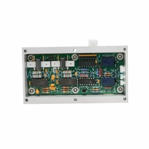
SKU: GIGA-F 0090-36221 0190-04562 H SK.CTD.200-0DEG F.D. 0040-95291
AMAT 0090-36221 Retrofit-Compatible TC Amp for Legacy Systems