Original Industrial Spare Part
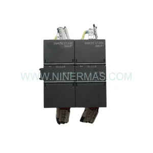
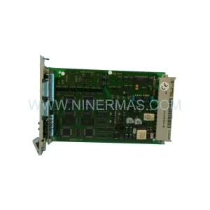
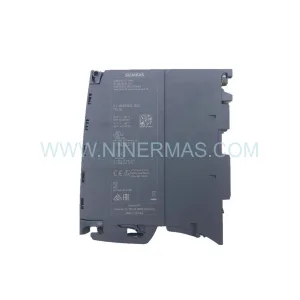
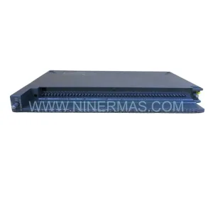
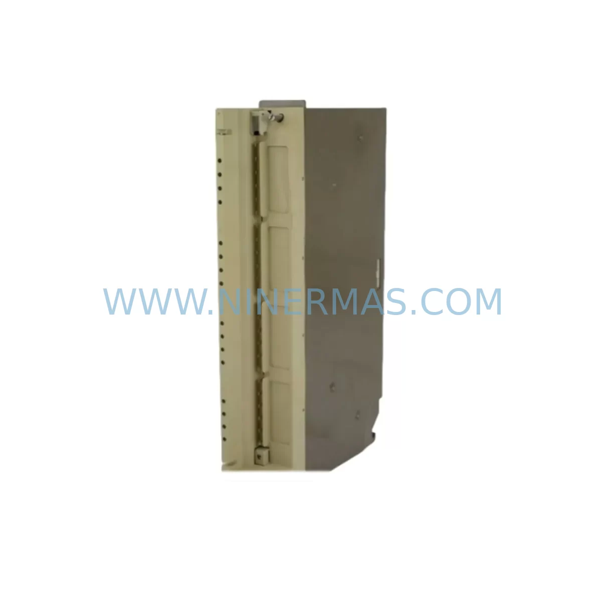
Siemens 6ES5432-7LA11 Retrofit-Compatible DI Module for Legacy Systems
Verify the part, confirm the platform family, and move straight into quotation with the right commercial details.
RFQ Ready
- SKU6ES5432-7LA11
- CategoryPLC & Industrial Automation Modules
- BrandSiemens
- SupportAvailability, lead time, condition, and shipping coordination
How Buyers Usually Use This Page
- Confirm the exact part number and platform family before sending the quote request.
- Use direct email when quantity, condition, and destination are already defined internally.
- Switch to the broader brand or category archive when you need alternates nearby.
Series Navigation
Move through the most common platform families behind this part.
Product RFQ
Send this part directly for quotation.
Include quantity, required condition, destination country, and target delivery timing. Current reference: Siemens 6ES5432-7LA11 Retrofit-Compatible DI Module for Legacy Systems with SKU 6ES5432-7LA11.
Siemens 6ES5432-7LA11 Retrofit-Compatible DI Module for Legacy Systems: Seamless Upgrade for Aging SIMATIC S5 Automation
The Siemens 6ES5432-7LA11 is a 32-channel digital input module originally designed for the SIMATIC S5 programmable controller family — one of the most widely deployed industrial automation platforms of the 1980s and 1990s. As production facilities worldwide continue to operate legacy S5-based control systems well beyond their original design life, the 6ES5432-7LA11 remains a critical spare part for maintaining operational continuity, reducing unplanned downtime, and extending the service life of existing control cabinets without requiring a full platform migration.
This module accepts 24 V DC digital input signals and interfaces directly with the S5 backplane bus, making it a direct retrofit replacement for failed or end-of-life units in existing S5-115U, S5-135U, and S5-155U rack configurations. Whether you are managing a planned maintenance window, responding to an emergency module failure, or executing a phased modernization of your production line, the 6ES5432-7LA11 provides the signal acquisition capability your legacy system depends on — without requiring changes to your existing STEP 5 program logic, terminal wiring, or HMI screen configurations.
Upgrade Compatibility Table
| Parameter | 6ES5432-7LA11 Specification | Retrofit Notes |
|---|---|---|
| Input Channels | 32 × 24 V DC digital inputs | Verify field device signal levels match 24 V DC nominal |
| Backplane Interface | S5 bus connector (parallel bus) | Compatible with S5-115U, S5-135U, S5-155U racks; confirm slot assignment in STEP 5 hardware configuration |
| Installation Format | S5 standard module form factor | Direct slot-for-slot replacement; no mechanical modification required |
| Terminal Wiring | Front connector (40-pin) | Reuse existing front connector and field wiring; verify terminal labeling against original I/O list |
| Module Address | Configured via DIP switch / slot address | Match address setting to original module; cross-reference STEP 5 program I/O assignments |
| Communication Protocol | S5 parallel backplane bus | No protocol migration required for like-for-like replacement; PROFIBUS or MPI not applicable at module level |
| Power Consumption | Supplied via S5 backplane (5 V DC bus) | Verify PS 951 or equivalent S5 power supply capacity covers total rack load including this module |
| Program Compatibility | STEP 5 (S5DOS / PG 740 / PG 760) | No program changes required for direct replacement; retain existing OB, FB, and DB structure |
| HMI Screen Impact | None (input module only) | No WinCC, ProTool, or OP panel screen updates required for like-for-like swap |
| Commissioning | Cold swap with power-off procedure | Follow S5 system manual lockout/tagout; perform I/O force test after replacement |
| Warranty | 12-Month Warranty — covers manufacturing defects; each unit ships after functional pre-shipment test | |
Retrofit Planning for Existing Automation Systems
Replacing the 6ES5432-7LA11 in an operating plant requires a structured approach that accounts for the interdependencies between the digital input module and the broader S5 control architecture. Before scheduling a maintenance window, engineers should audit the full rack configuration to identify all modules sharing the same backplane — typically a combination of digital output modules such as the 6ES5430-7LA12 or 6ES5431-7LA12, analog input modules like the 6ES5464-8ME11, and the central processing unit, most commonly a CPU 948 (6ES5948-3UA23) or CPU 928B (6ES5928-3UB21) in larger S5-155U installations.
Power supply capacity is a frequent oversight in retrofit projects. The S5 power supply module — typically a PS 951 (6ES5951-7LB21) or PS 955 (6ES5955-3LC41) — must be verified to provide sufficient 5 V DC bus current for the complete rack load after the replacement module is installed. If the existing power supply is already operating near its rated output, this is an opportunity to evaluate whether a higher-capacity replacement or a supplementary 24 V DC field power supply is warranted before the retrofit proceeds.
Terminal wiring is another critical checkpoint. The 6ES5432-7LA11 uses a 40-pin front connector that carries all 32 input channels plus common and shield connections. In most installations, this front connector can be unplugged from the failed module and transferred directly to the replacement unit without disturbing field wiring — provided the connector locking mechanism is intact and the terminal screws have not been over-torqued. Engineers should photograph the existing wiring layout and cross-reference against the original I/O list before disconnecting anything.
Module address configuration must be verified before the replacement module is powered up. On S5 systems, the slot position on the rack determines the I/O address range assigned to the module. If the replacement 6ES5432-7LA11 is installed in the same physical slot as the original, the address assignment will be preserved automatically. However, if the rack layout has been modified since the original installation — for example, due to the addition of a SINEC L2 communication processor or a CP 5431 PROFIBUS module — the address map should be reviewed in the STEP 5 hardware configuration before commissioning.
For facilities that are using this replacement as a stepping stone toward a broader migration to SIMATIC S7-300 or S7-400 platforms, the retrofit of the 6ES5432-7LA11 can be combined with the installation of a IM 463-2 interface module or a S5-to-S7 migration coupler to allow parallel operation of legacy S5 I/O alongside new S7 hardware during the transition period. In such scenarios, the existing STEP 5 program can be converted using the SIMATIC S5/S7 Converting Tool, and the HMI screens on connected OP 17 or OP 27 operator panels can be migrated to WinCC flexible or TIA Portal HMI projects without requiring a full production shutdown.
Downtime Control During System Migration
Minimizing downtime during a 6ES5432-7LA11 replacement begins with preparation. A well-executed swap can be completed in under 30 minutes if the replacement module is on-site, the front connector is pre-labeled, and the maintenance team has reviewed the STEP 5 program structure in advance. The most time-consuming steps are typically the lockout/tagout procedure, the I/O force test after replacement, and the verification of all 32 input channels against the field device list.
To protect the original program logic, a full STEP 5 program backup should be performed before any hardware changes are made. This backup should be stored on both the programming device — typically a PG 740 or PG 760 — and on an external storage medium. If the CPU has a memory card (EPROM or RAM cartridge), the program should also be verified on the card before the maintenance window begins. This ensures that if the CPU loses its program during the power cycle associated with the module swap, the program can be reloaded immediately without requiring a programmer to be on-site.
For critical production lines where even a 30-minute outage is unacceptable, a hot-standby approach using a redundant S5 rack with a pre-configured 6ES5432-7LA11 in a shadow slot can be considered. This approach requires that the control system architecture supports redundant I/O — a configuration more common in S5-155U installations with IM 304/IM 314 interface modules connecting remote I/O racks. In such configurations, the failed module can be replaced in the remote rack while the redundant rack continues to supply inputs to the CPU, eliminating the need for a production stop entirely.
After the replacement module is installed and powered up, the commissioning sequence should include a channel-by-channel I/O force test using the STEP 5 programming software to verify that all 32 input channels are reading correctly. Any discrepancies between the expected and actual input states should be investigated before the system is returned to automatic mode. Common causes of post-replacement discrepancies include incorrect front connector seating, damaged field wiring exposed during the swap, and address conflicts caused by incorrect DIP switch settings on the replacement module.
Retrofit Support FAQ
Q1: Is the 6ES5432-7LA11 a direct drop-in replacement for the original module in my S5 rack?
Yes. The 6ES5432-7LA11 is a direct slot-for-slot replacement for any failed or end-of-life unit of the same part number in an S5-115U, S5-135U, or S5-155U rack. No mechanical modification, program change, or HMI update is required for a like-for-like swap. Transfer the existing 40-pin front connector from the old module to the replacement unit, verify the DIP switch address settings match the original, and the system will resume normal operation after power-up.
Q2: What pre-shipment testing is performed on each unit?
Every 6ES5432-7LA11 supplied by NINERMAS undergoes a functional pre-shipment test that verifies backplane bus communication, channel-by-channel input response, and power consumption within specification. Units that fail any test parameter are quarantined and not shipped. A test report is available upon request. All units are covered by a 12-month warranty against manufacturing defects from the date of shipment.
Q3: How do I verify wiring compatibility before installing the replacement module?
Before installing the replacement 6ES5432-7LA11, photograph the existing front connector wiring and cross-reference each terminal against the original I/O list and the S5 system wiring diagram. Verify that all field device signal levels are within the 24 V DC nominal input range specified for this module. Check that the front connector locking mechanism is undamaged and that no terminal screws are stripped. If the original front connector is damaged, a replacement 40-pin front connector should be sourced and re-wired before the module swap proceeds.
Q4: What is the stock availability and lead time for the 6ES5432-7LA11?
NINERMAS maintains inventory of the 6ES5432-7LA11 to support emergency replacement and planned maintenance requirements. In-stock units are typically dispatched within 1–2 business days of order confirmation. For bulk orders or long-term spare parts supply agreements covering multiple S5 modules — including digital output modules, analog I/O modules, CPU units, and power supplies — please contact our sales team to discuss pricing, lead times, and 12-month warranty terms tailored to your maintenance schedule.
| Product Series | SIMATIC S5 |
|---|---|
| Country of Origin | DE |
Catalog Continuation
More Siemens modules in the catalog.
Use the brand lane to compare nearby part numbers, platform-adjacent modules, and other inquiry-ready listings before sending your final RFQ.
SKU: 6SE7090-0XX87-4AH0
SIEMENS 6SE7090-0XX87-4AH0 Retrofit Communication Module
SKU: 6ES7341-1AH01-0AE0
Siemens 6ES7341-1AH01-0AE0 Retrofit-Compatible CP341 for Legacy Systems
SKU: 6SL3352-3AG35-8AA0
Siemens 6SL3352-3AG35-8AA0 Service-Ready Spare Part for Industrial Maintenance
SKU: 6SY7000-0AA31
SIEMENS 6SY7000-0AA31 Retrofit-Compatible Rectifier Unit
Catalog Continuation
Alternative parts within PLC & Industrial Automation Modules.
Stay inside the same system family when you need substitutes, adjacent modules, or a broader shortlist for procurement review.
SKU: GIGA-F 0090-36221 0190-04562 H SK.CTD.200-0DEG F.D. 0040-95291
AMAT 0090-36221 Retrofit-Compatible TC Amp for Legacy Systems