Original Industrial Spare Part
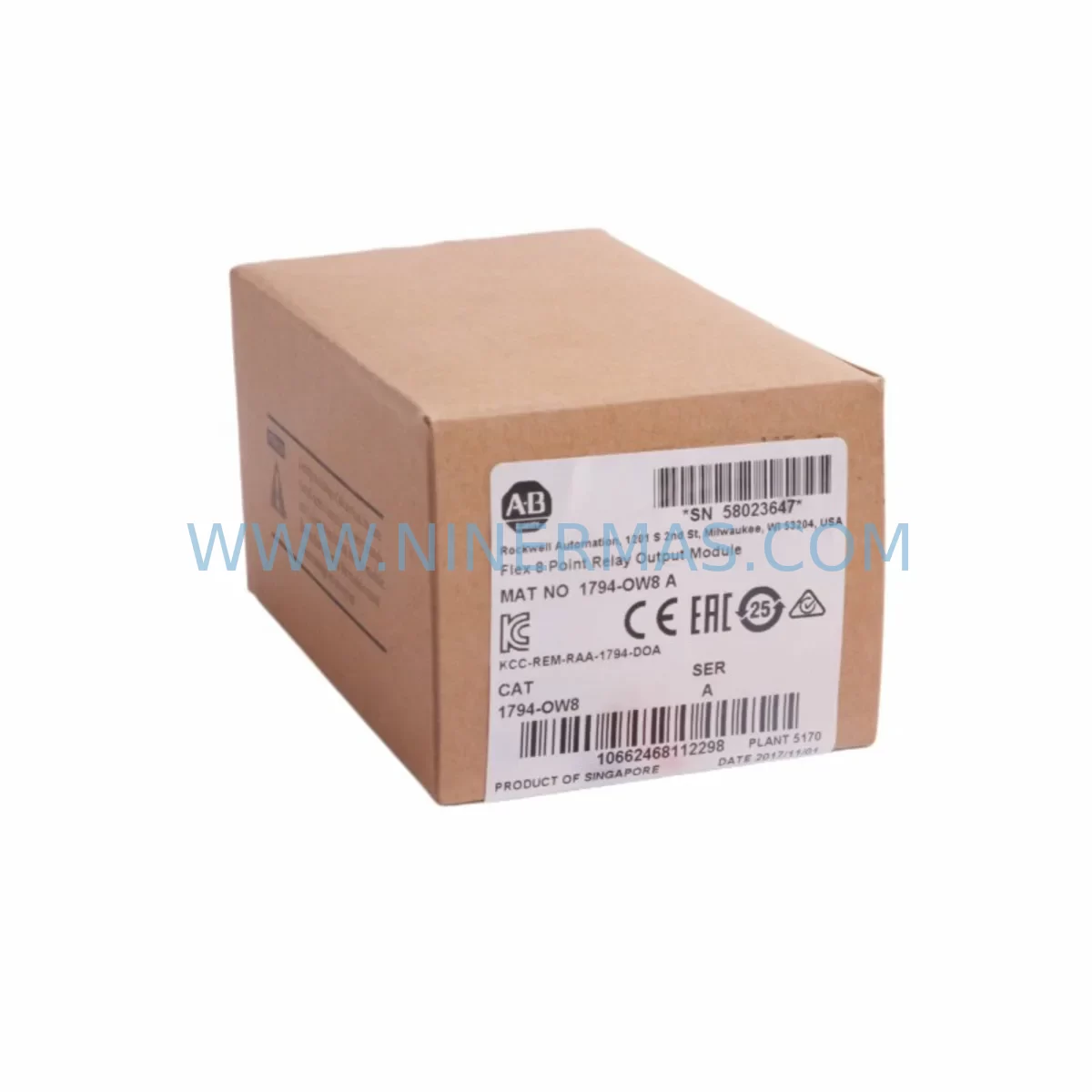
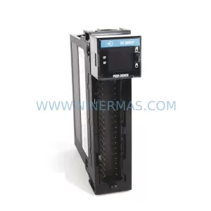
Allen-Bradley 1794-OW8 Service-Ready Spare Part for Industrial Maintenance
Verify the part, confirm the platform family, and move straight into quotation with the right commercial details.
RFQ Ready
- SKU1794-OW8
- CategoryPLC & Industrial Automation Modules
- BrandAllen-Bradley
- SupportAvailability, lead time, condition, and shipping coordination
How Buyers Usually Use This Page
- Confirm the exact part number and platform family before sending the quote request.
- Use direct email when quantity, condition, and destination are already defined internally.
- Switch to the broader brand or category archive when you need alternates nearby.
Series Navigation
Move through the most common platform families behind this part.
Product RFQ
Send this part directly for quotation.
Include quantity, required condition, destination country, and target delivery timing. Current reference: Allen-Bradley 1794-OW8 Service-Ready Spare Part for Industrial Maintenance with SKU 1794-OW8.
Allen-Bradley 1794-OW8 Service-Ready Spare Part for Industrial Maintenance
The Allen-Bradley 1794-OW8 is an 8-point relay output module designed for the Rockwell Automation FLEX I/O platform — one of the most widely deployed distributed I/O systems in discrete manufacturing, process control, and material handling environments worldwide. As production lines age and OEM support windows close, maintaining a verified stock of the 1794-OW8 becomes a critical element of any proactive maintenance strategy. Whether you are managing a high-availability bottling line, a conveyor-driven assembly cell, or a legacy PLC-controlled packaging system, the 1794-OW8 delivers the relay switching reliability that field engineers depend on for fast, low-risk restoration of output control circuits.
At NINERMAS, every 1794-OW8 unit is sourced, inspected, and dispatched with full traceability. Our inventory supports maintenance engineers and procurement teams across Asia, Europe, and the Americas who require original-specification spare parts with short lead times, consistent availability, and a 12-month warranty covering functional defects under normal operating conditions.
Spare Maintenance Table
| Parameter | Specification |
|---|---|
| Part Number | 1794-OW8 |
| Brand / Manufacturer | Allen-Bradley / Rockwell Automation |
| Series | FLEX I/O (1794 Series) |
| Module Type | Discrete Relay Output Module |
| Number of Output Points | 8 relay output points |
| Output Voltage Range | 5–265V AC / 5–125V DC |
| Max Output Current per Point | 2A (resistive load) |
| Isolation | Optical isolation between field side and backplane |
| Backplane Compatibility | 1794-TB2, 1794-TB3, 1794-TB3S terminal bases |
| Communication Compatibility | DeviceNet (1794-ADN), EtherNet/IP (1794-AENT), ControlNet (1794-ACN) |
| Operating Temperature | 0°C to 55°C (32°F to 131°F) |
| Relative Humidity | 5–95% non-condensing |
| Mounting | DIN rail via FLEX I/O terminal base |
| Certifications | UL, CE, CSA |
| Origin | United States |
| Warranty | 12 months from shipment date |
| Pre-shipment Testing | Functional output switching test performed on every unit |
| Condition | New / Surplus New |
Maintenance Planning for Continuous Operation
Replacing the 1794-OW8 in a live control cabinet is rarely an isolated task. Experienced maintenance engineers understand that a failed relay output module is often a symptom of broader electrical stress in the I/O subsystem. When scheduling a 1794-OW8 replacement — whether during an emergency callout or a planned annual shutdown — the following associated components should be inspected, tested, or staged as co-replacement candidates.
Begin with the terminal base. The 1794-OW8 mounts onto a dedicated FLEX I/O terminal base such as the 1794-TB3 or 1794-TB3S. Corroded or cracked terminal bases are a leading cause of intermittent output faults that are incorrectly attributed to the module itself. Inspect the backplane connector pins for oxidation and verify torque on all field wiring terminals before inserting the replacement module.
Next, evaluate the FLEX I/O adapter that manages communication between the I/O bank and the controller. Common adapters in 1794-series installations include the 1794-AENT (EtherNet/IP), 1794-ADN (DeviceNet), and 1794-ACN15 (ControlNet). A degraded adapter can cause the new 1794-OW8 to appear faulted even after correct installation. Confirm adapter firmware version compatibility and check for any active fault codes in the controller’s I/O tree before closing the cabinet.
On the power side, verify the FLEX I/O power supply — typically a 1794-PS13 or equivalent 24VDC rail supply — is delivering stable voltage within specification. Relay output modules are sensitive to power rail noise, and an undersized or aging power supply can cause erratic relay chatter or premature contact wear. If the installation uses a shared 24VDC bus, also inspect the terminal block fuse holders and any miniature circuit breakers protecting individual output circuits.
For installations where the 1794-OW8 drives inductive loads such as solenoid valves, motor starters, or contactor coils, check the surge suppression devices (RC snubbers or varistors) wired across each load. Missing or failed suppressors dramatically shorten relay contact life and can introduce voltage spikes that damage adjacent I/O modules. This is particularly important in older panels where suppression components may have been omitted during original commissioning.
If the control system includes signal isolators or interposing relay modules between the 1794-OW8 outputs and field devices, inspect these for contact wear and coil resistance. Brands such as Phoenix Contact, Weidmüller, and Finder produce widely used interposing relay bases that are often overlooked during I/O module replacements. A worn interposing relay can mask a healthy output module and lead to unnecessary repeat callouts.
For systems running on ControlLogix or CompactLogix platforms, confirm that the I/O configuration in Studio 5000 Logix Designer matches the replacement module’s electronic keying settings. Incorrect keying configuration will prevent the module from going online. If the installation uses RSLogix 5000 on an older controller revision, verify that the 1794-OW8 catalog number and revision are correctly mapped in the I/O tree before energizing the output bank.
Finally, for sites managing aging FLEX I/O installations beyond their original design life, consider staging a 1794-OW8 alongside a spare 1794-IB16 (16-point DC input module) and a 1794-OB16 (16-point DC output module) as part of a comprehensive I/O bank spare kit. This approach reduces mean time to repair (MTTR) across the most common failure modes in a single cabinet and supports procurement teams in consolidating purchase orders for annual maintenance budgets.
Site Replacement Workflow
Step 1 — Pre-replacement verification: Before removing the existing module, record the current I/O status in the controller software. Note any active output states that must be restored after replacement. If the system supports partial fault mode, confirm whether outputs will de-energize during the swap.
Step 2 — Safe isolation: Isolate the field-side power feeding the relay output circuits. Do not rely solely on the controller’s output inhibit function. Use a lockout/tagout (LOTO) procedure appropriate for the voltage levels present on the terminal base.
Step 3 — Module removal: Slide the 1794-OW8 out of the terminal base. Inspect the backplane connector on both the module and the terminal base for damage, contamination, or bent pins. Clean with appropriate contact cleaner if required.
Step 4 — Replacement module inspection: Confirm the replacement 1794-OW8 catalog number, series letter, and firmware revision match the removed unit or are compatible with the controller’s I/O configuration. NINERMAS provides full catalog and series documentation with every shipment.
Step 5 — Installation and keying check: Insert the replacement module into the terminal base. Confirm the electronic keying LED or controller diagnostic indicates a healthy module status. In Studio 5000, the module should transition from Faulted to Running within one communication scan cycle.
Step 6 — Output verification: Restore field-side power and perform a point-by-point output test using the controller’s forced I/O function or a dedicated test routine. Confirm each relay closes and opens correctly under load before returning the system to automatic operation.
Step 7 — Documentation: Update the maintenance log with the replacement date, module serial number, and any observations noted during the swap. Record the spare parts consumed and initiate a replenishment purchase order to restore buffer stock levels.
Spare Parts Support FAQ
Q1: Is the 1794-OW8 still available as a new or surplus-new unit, and what is the lead time?
Yes. NINERMAS maintains stock of the 1794-OW8 in new and surplus-new condition. Standard lead time for in-stock units is 3–7 business days for international shipments. For urgent requirements, expedited air freight options are available. Contact sale@ninermas.com with your required quantity and delivery location for a same-day quotation.
Q2: How do I confirm compatibility between the 1794-OW8 and my existing FLEX I/O terminal base and adapter?
The 1794-OW8 is compatible with all standard 1794-series terminal bases including the 1794-TB2, 1794-TB3, and 1794-TB3S. It operates with all FLEX I/O communication adapters (EtherNet/IP, DeviceNet, ControlNet, and PROFIBUS). Confirm the electronic keying setting in your controller configuration matches the replacement module’s catalog number and series. NINERMAS can provide the module’s series letter and revision documentation prior to shipment upon request.
Q3: What testing is performed before the 1794-OW8 is shipped?
Every 1794-OW8 unit dispatched by NINERMAS undergoes a functional relay switching test to verify all 8 output points operate correctly. Units are inspected for physical damage, connector integrity, and label legibility. A 12-month warranty covering functional defects under normal operating conditions is included with every shipment. Warranty claims are processed directly through NINERMAS with no requirement to contact the original manufacturer.
Q4: Can NINERMAS support long-term or blanket purchase orders for the 1794-OW8 as part of an annual maintenance contract?
Yes. NINERMAS supports long-term supply agreements for maintenance teams and MRO procurement departments that require guaranteed availability of critical spare parts. Blanket orders, scheduled releases, and consignment stock arrangements can be discussed based on your annual consumption volume. Contact our sales team at sale@ninermas.com or +0086 187 5021 5667 to discuss a supply agreement tailored to your maintenance program.
| Product Series | ControlLogix |
|---|---|
| Country of Origin | US |
Catalog Continuation
More Allen-Bradley modules in the catalog.
Use the brand lane to compare nearby part numbers, platform-adjacent modules, and other inquiry-ready listings before sending your final RFQ.
Catalog Continuation
Alternative parts within PLC & Industrial Automation Modules.
Stay inside the same system family when you need substitutes, adjacent modules, or a broader shortlist for procurement review.
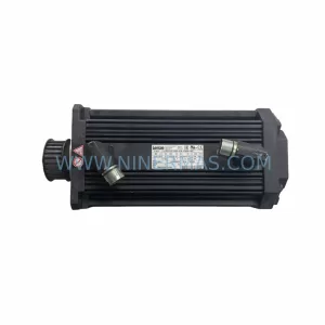
SKU: 14L41-RS0B0-B24R-ST5S00N-R0SU
LENZE 14L41-RS0B0-B24R-ST5S00N-R0SU Retrofit for Legacy Systems
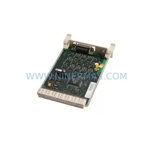
SKU: CI540 3BSE001077R1
ABB CI540 3BSE001077R1 Spare Part for Industrial Maintenance
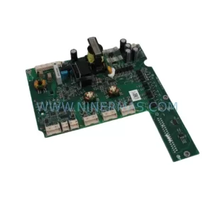
SKU: ZINT-541 3AUA00000658960
ABB ZINT-541 3AUA00000658960 Retrofit-Compatible Inverter Power Module
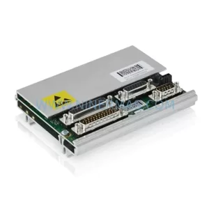
SKU: DSQC633 3HAC022286-001
ABB DSQC633 3HAC022286-001 Service-Ready Spare Part