Original Industrial Spare Part
MITSUBISHI AY40 Retrofit-Compatible Output Module
Verify the part, confirm the platform family, and move straight into quotation with the right commercial details.
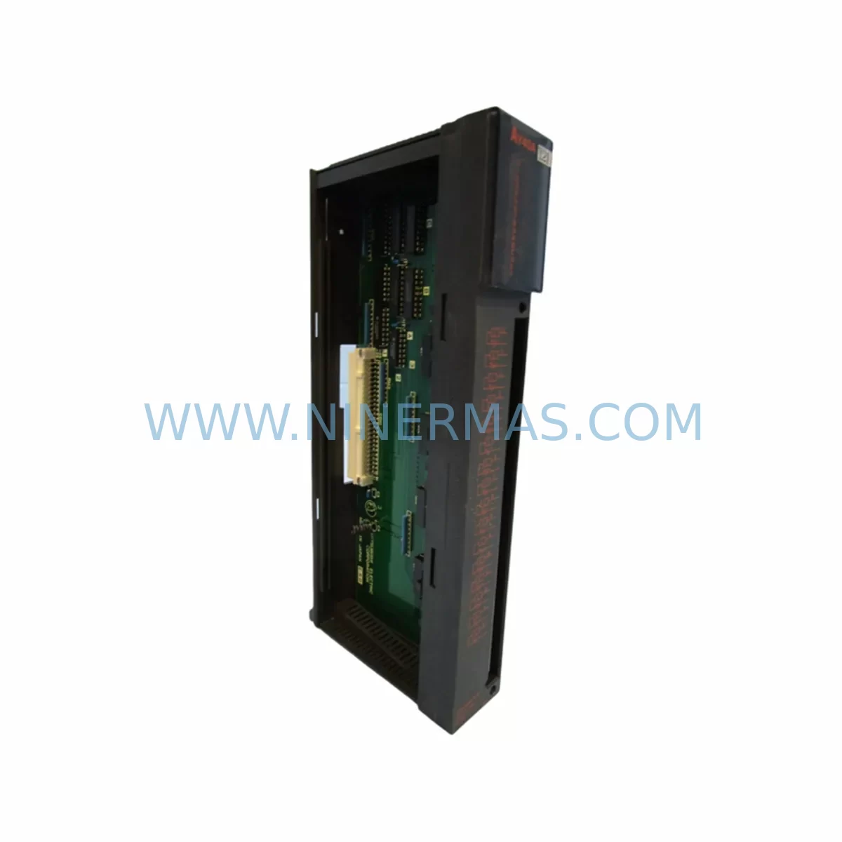
RFQ Ready
- SKUAY40
- CategoryPLC & Industrial Automation Modules
- BrandMitsubishi
- SupportAvailability, lead time, condition, and shipping coordination
How Buyers Usually Use This Page
- Confirm the exact part number and platform family before sending the quote request.
- Use direct email when quantity, condition, and destination are already defined internally.
- Switch to the broader brand or category archive when you need alternates nearby.
Series Navigation
Move through the most common platform families behind this part.
Product RFQ
Send this part directly for quotation.
Include quantity, required condition, destination country, and target delivery timing. Current reference: MITSUBISHI AY40 Retrofit-Compatible Output Module with SKU AY40.
MITSUBISHI AY40 Retrofit-Compatible Output Module for Legacy MELSEC A-Series Systems
The MITSUBISHI AY40 is a transistor output module designed for the MELSEC A-Series programmable logic controller platform. As legacy A-Series installations approach end-of-life and original spare parts become increasingly scarce, the AY40 remains one of the most sought-after retrofit components for engineers tasked with sustaining aging production lines, upgrading control cabinets, or executing a phased migration to modern Mitsubishi platforms such as the MELSEC Q-Series or iQ-R Series.
The AY40 provides 16-point transistor (sink) output capability, making it directly applicable to a wide range of discrete output applications including solenoid valve control, relay coil driving, indicator lamp circuits, and motor starter interfaces. Its compact form factor and standard A-Series backplane pinout allow it to be installed into existing A-Series base units — such as the A1S38B or A1S52B — without mechanical modification, provided the power budget of the installed power supply module (e.g., A1S61P or A1S62P) is verified against the total module load.
When planning a retrofit or spare part replacement using the AY40, engineers should confirm several critical parameters before committing to installation. First, verify the output commons and load voltage range against the field wiring already terminated on the existing terminal block. The AY40 supports a 12–24 VDC load voltage range on its output commons, and any mismatch with existing field devices will require rewiring or the insertion of a signal isolator module between the PLC output and the field load. Second, confirm the slot address assignment within the A-Series base unit, as the CPU module — typically an A2SHCPU, A3NCPU, or A1SCPU — must have its I/O assignment table updated in GX Developer or GX Works2 to reflect the new module’s position and output point count. Failure to update the I/O map will result in incorrect output addressing and potential process faults at startup.
For installations where the AY40 is replacing a failed or discontinued output module mid-production, downtime control is paramount. Experienced retrofit engineers typically pre-stage the replacement module on a bench, verify its output continuity using a 24 VDC test source, and prepare a printed copy of the existing I/O wiring diagram before entering the control cabinet. The original program logic stored in the CPU does not need to be modified if the replacement module occupies the same slot and carries the same point count — the AY40’s 16-point configuration is directly compatible with the original A-Series I/O assignment for this module type.
Upgrade Compatibility Table
| Parameter | MITSUBISHI AY40 Specification | Retrofit / Replacement Notes |
|---|---|---|
| Output Type | Transistor (Sink), 16 Points | Verify field wiring polarity before installation |
| Load Voltage | 12–24 VDC | Confirm against existing field device voltage |
| Backplane Interface | MELSEC A-Series Standard Slot | Compatible with A1S38B, A1S52B, A1S65B base units |
| Communication Compatibility | A-Series CPU Bus | No protocol migration required for same-platform replacement |
| Installation Space | Single-slot module | Direct drop-in; no mechanical modification required |
| Program Compatibility | GX Developer / GX Works2 | I/O assignment table update required if slot address changes |
| Replacement Path | AY40 → AY40-UL or Q-Series QY40P (with adapter) | QY40P requires A1SJ71QLP21 or equivalent bus converter |
| Pre-Shipment Testing | Yes — output continuity and load switching verified | Test report available on request |
| Warranty | 12 Months | Covers manufacturing defects and functional failure |
Retrofit Planning for Existing Automation Systems
A successful AY40 retrofit begins well before the module arrives on-site. The engineering team should audit the full A-Series rack configuration, documenting each installed module by slot position, type, and I/O address range. In a typical A-Series control cabinet, the rack may include a combination of input modules such as the AX40 or AX80, analog I/O modules such as the A68AD or A62DA, and communication modules such as the A1SJ71UC24-R4 for RS-232C/RS-422 serial links or the A1SJ71E71-B5 for Ethernet connectivity. Each of these modules must remain undisturbed during the AY40 replacement to avoid disrupting the overall I/O map.
Power supply capacity is a frequent oversight in retrofit planning. The A1S61P and A1S62P power supply modules each carry defined output current ratings for the 5 VDC backplane bus. Adding or replacing output modules — particularly those with higher inrush current profiles — can push the power supply toward its rated limit. Engineers should calculate the total 5 VDC consumption of all installed modules and confirm that the existing power supply has sufficient headroom before installing the AY40.
For systems where the A-Series CPU is being retained but the output module is being upgraded, the HMI interface — often a Mitsubishi GOT1000 or GOT2000 series panel — does not require reprogramming, provided the output device addresses referenced in the HMI project remain unchanged. If the AY40 replacement results in a slot address shift, the corresponding Y-device addresses in the GOT screen project must be updated using GT Designer3 before the system is returned to service.
In multi-rack configurations using an A1SJ71LP21 or A1SJ71BR11 MELSECNET/10 link module, the network station address and I/O assignment for the rack containing the AY40 must be verified in the network parameter settings of the master CPU. Incorrect station addressing after a module swap is a common cause of communication faults that can be mistaken for hardware failure.
Where the retrofit scope extends beyond a single module replacement — for example, when upgrading an entire A-Series rack to Q-Series — the AY40 is typically replaced by the QY40P transistor output module, which requires a QA1S6ADP slot adapter and a QA6ADP base adapter to interface with the existing A-Series wiring harness. This approach preserves the original field wiring and terminal block layout while introducing Q-Series processing speed and expanded diagnostic capability. The programming environment transitions from GX Developer ladder logic to GX Works2 or GX Works3, and the I/O refresh cycle and interrupt response times must be re-validated against the process requirements of the controlled equipment.
Downtime Control During System Migration
Minimizing unplanned downtime during an AY40 replacement or A-Series system migration requires a structured approach that protects the original program logic, maintains field control continuity, and reduces the risk of commissioning errors. The following practices are recommended for industrial sites where production continuity is critical.
Before any hardware is removed, perform a full program backup from the CPU using GX Developer or GX Works2 and store the project file in at least two separate locations — one on the engineering laptop and one on a network share or USB drive. Verify that the backup reads back correctly by comparing the program checksum or step count against the original. This step is non-negotiable: A-Series CPUs that have been in service for extended periods may have battery-backed RAM that is approaching the end of its retention capacity, and a power interruption during module removal can result in program loss if the backup has not been confirmed.
Where the process allows, schedule the AY40 replacement during a planned maintenance window rather than as an emergency repair. Pre-stage the replacement module, verify its output points using a 24 VDC bench test, and prepare a wiring diagram marked with the terminal numbers and load descriptions for each of the 16 output points. During installation, work systematically from terminal 0 to terminal 15, reconnecting each field wire and verifying continuity before powering the system.
After installation, perform a controlled power-up sequence: energize the power supply module first, confirm the CPU enters RUN mode without error LEDs, then enable outputs in a test sequence using the GX Developer monitor function before returning the system to automatic operation. If the AY40 is installed in a system that uses a watchdog timer or external safety relay — such as an A1S-series safety module or an external Pilz or Omron safety relay — confirm that the safety circuit is re-armed and verified before resuming production.
For sites where a cold standby spare is maintained, the AY40 should be stored in its original anti-static packaging in a temperature-controlled environment. Mitsubishi A-Series modules are sensitive to electrostatic discharge and humidity, and improper storage can degrade the output transistor junctions over time, resulting in latent failures that only manifest under load.
Retrofit Support FAQ
Q: Is the MITSUBISHI AY40 a direct drop-in replacement for a failed output module in my A-Series rack?
A: Yes, provided the failed module is also a 16-point transistor sink output type and occupies the same slot position. The AY40 uses the standard A-Series backplane connector and does not require any mechanical modification. If the slot address changes, update the I/O assignment table in GX Developer before returning the CPU to RUN mode.
Q: What commissioning steps are required after installing the AY40?
A: After physical installation and field wiring reconnection, power up the system and confirm the CPU enters RUN mode without I/O error codes. Use the GX Developer or GX Works2 monitor function to force each output point individually and verify the corresponding field device responds correctly. Check the output commons for correct voltage and confirm that all 16 output points switch cleanly under load before enabling automatic operation.
Q: Has the AY40 been tested before shipment?
A: Yes. Each AY40 unit undergoes pre-shipment output continuity and load switching verification before dispatch. A test report is available on request. All units are supplied with a 12-month warranty covering manufacturing defects and functional failure under normal operating conditions.
Q: What is the recommended upgrade path if I need to migrate from A-Series to Q-Series?
A: The recommended replacement for the AY40 in a Q-Series migration is the QY40P transistor output module. This requires a QA1S6ADP slot adapter and a QA6ADP base adapter to interface with the existing A-Series wiring. The field wiring and terminal block layout can be preserved. Programming must be migrated from GX Developer to GX Works2 or GX Works3, and I/O addresses must be remapped to the Q-Series device numbering convention.
| Product Series | MELSEC |
|---|---|
| Country of Origin | JP |
Catalog Continuation
More Mitsubishi modules in the catalog.
Use the brand lane to compare nearby part numbers, platform-adjacent modules, and other inquiry-ready listings before sending your final RFQ.
SKU: QX48Y57 BD627B662G51
Mitsubishi QX48Y57 BD627B662G51 Spare Part MELSEC
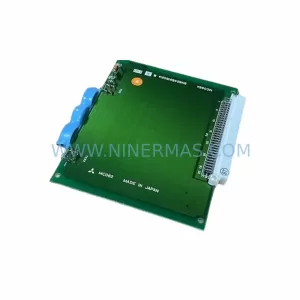
SKU: MC062A BN624B816G51A
Mitsubishi MC062A BN624B816G51A Spare Part Industrial
Catalog Continuation
Alternative parts within PLC & Industrial Automation Modules.
Stay inside the same system family when you need substitutes, adjacent modules, or a broader shortlist for procurement review.
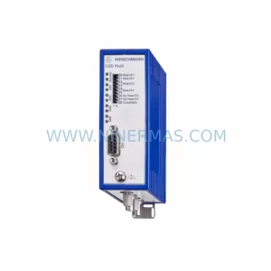
SKU: OZDPROFI12MG12
Hirschmann OZDPROFI12MG12 Spare Part for Industrial Maintenance
SKU: 07025-0000-70-1-04
KONTRON 07025-0000-70-1-04 Service-Ready Spare Part