Original Industrial Spare Part
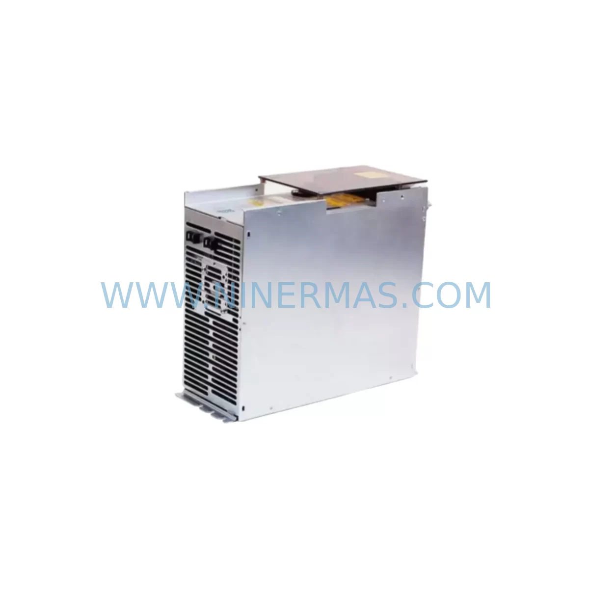
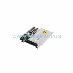
Bosch TVD1.2-08-03 Retrofit-Compatible DC Supply Module
Verify the part, confirm the platform family, and move straight into quotation with the right commercial details.
RFQ Ready
- SKUTVD1.2-08-03
- CategoryPLC & Industrial Automation Modules
- BrandBosch
- SupportAvailability, lead time, condition, and shipping coordination
How Buyers Usually Use This Page
- Confirm the exact part number and platform family before sending the quote request.
- Use direct email when quantity, condition, and destination are already defined internally.
- Switch to the broader brand or category archive when you need alternates nearby.
Series Navigation
Move through the most common platform families behind this part.
Product RFQ
Send this part directly for quotation.
Include quantity, required condition, destination country, and target delivery timing. Current reference: Bosch TVD1.2-08-03 Retrofit-Compatible DC Supply Module with SKU TVD1.2-08-03.
Bosch TVD1.2-08-03 Retrofit-Compatible DC Supply Module: Legacy System Compatibility and Smooth Upgrade
The Bosch TVD1.2-08-03 is a DC power supply module designed for use within the Bosch Rexroth DIAX02 and DIAX04 drive system platforms. As original equipment reaches end-of-life and OEM support is discontinued, the TVD1.2-08-03 has become a critical retrofit and replacement component for industrial facilities operating legacy servo drive cabinets, CNC machining centres, and automated production lines. NINERMAS maintains verified stock of the TVD1.2-08-03 to support planned maintenance shutdowns, emergency replacements, and long-term spare parts programs across processing, automotive, and precision manufacturing industries.
The TVD1.2-08-03 functions as the mains supply unit within a Rexroth drive group, converting AC input power into the regulated DC bus voltage required by connected drive controllers such as the HDS, HDD, and DDS series modules. When replacing a failed or degraded supply module, engineers must confirm the DC bus voltage rating, peak current capacity, and the physical form factor against the existing drive cabinet layout. The TVD1.2-08-03 occupies a standard Rexroth drive rail slot and interfaces with adjacent drive modules through the DC bus bar connection — a critical mechanical and electrical interface that must be verified before installation to avoid bus bar misalignment or contact resistance issues.
Upgrade Compatibility Table
| Parameter | TVD1.2-08-03 Specification | Retrofit / Replacement Notes |
|---|---|---|
| Module Type | DC Mains Supply Unit | Replaces failed or end-of-life TVD1.2 series supply modules in DIAX02/DIAX04 drive groups |
| Compatible Drive Series | HDS, HDD, DDS (Bosch Rexroth) | Verify drive group configuration; mixed HDS/DDS groups require bus bar continuity check |
| DC Bus Interface | Rexroth standard DC bus bar | Inspect bus bar contacts for oxidation or deformation before module insertion |
| Mains Input | 3-phase AC (confirm voltage range per nameplate) | Confirm site supply voltage and phase sequence before energising |
| Installation Format | Drive rail / cabinet panel mount | Confirm available cabinet depth and rail spacing; no modification required for standard Rexroth cabinets |
| Communication Interface | SERCOS / analogue interface (drive-dependent) | Supply module does not carry SERCOS fibre; verify fibre ring continuity on adjacent HDS/DDS modules |
| Firmware / Parameter | No firmware on supply module | Drive controller parameters (P-0-xxxx) are unaffected by supply module swap |
| Cooling Requirement | Forced air / cabinet ventilation | Confirm cabinet fan operation and filter condition before commissioning replacement module |
| Warranty | 12-Month Warranty — covers manufacturing defects and functional failure under normal operating conditions | |
Retrofit Planning for Existing Automation Systems
Replacing the TVD1.2-08-03 in an active production environment requires a structured approach to minimise risk and ensure a clean handover between the legacy supply module and the replacement unit. The supply module sits at the head of the drive group and feeds DC bus power to all downstream drive controllers. A failure or degraded performance in the TVD1.2-08-03 will typically manifest as DC bus undervoltage faults across the connected HDS or DDS drive modules, triggering E-stop conditions and halting the axis group.
Before scheduling the replacement, maintenance engineers should pull the existing drive group parameter backup using the IndraWorks DS or IndraWorks ML engineering software connected via the RS-232 or USB-to-serial programming cable. This backup captures all axis-specific parameters stored in the HDS and DDS drive controllers — parameters that govern current limits, velocity loops, encoder feedback scaling, and homing sequences. The supply module itself does not store drive parameters, but the replacement procedure creates an opportunity to audit the full drive group configuration and update any parameters that have drifted from the original commissioning values.
The physical replacement sequence begins with isolating the cabinet at the main disconnect, discharging the DC bus capacitors (allow a minimum of five minutes after isolation before touching bus bar connections), and then removing the TVD1.2-08-03 by releasing the drive rail locking mechanism. The replacement module slides into the same rail position and connects to the DC bus bar, the mains terminal block (L1, L2, L3, PE), and the 24 VDC control supply. The 24 VDC control rail — typically supplied by a separate Bosch PSI or PST series 24V power supply unit — must remain stable throughout the swap to preserve the control logic state in the connected PLC or CNC controller.
In systems where the TVD1.2-08-03 drives a mixed group including both HDS spindle drive modules and DDS servo drive modules, engineers should verify that the DC bus bar segments are correctly bridged and that the bus bar end cap is in place on the final module in the group. Missing or damaged bus bar end caps are a common source of DC bus instability after a module replacement. Similarly, the SERCOS fibre optic ring — connecting the CNC controller (such as a Bosch CC220, CC300, or BTV series operator panel) to the HDS and DDS modules — should be inspected for fibre continuity and connector cleanliness before re-energising the drive group.
For facilities running Bosch MTX or Rexroth IndraMotion MTX CNC platforms, the axis configuration in the CNC controller references each drive by its SERCOS address. After replacing the supply module, confirm that the SERCOS ring re-establishes correctly and that all drive addresses are recognised by the controller before releasing the machine for production. If the system includes a Rexroth HMI (such as a VDP or VEP operator panel) or a third-party HMI connected via Profibus DP or Ethernet, verify that the HMI communication link is restored and that axis status displays are reading correctly.
Facilities that operate multiple Rexroth drive cabinets — for example, a transfer line with separate drive groups for each machining station — should maintain a minimum of one TVD1.2-08-03 as a dedicated on-site spare. The lead time for sourcing discontinued Bosch Rexroth supply modules through standard distribution channels can extend to several weeks; maintaining a verified spare eliminates this risk and supports a same-shift recovery from an unplanned supply module failure.
Downtime Control During System Migration
Controlling downtime during a TVD1.2-08-03 replacement depends on preparation quality. The single most effective measure is completing the parameter backup, spare module verification, and tooling preparation before the maintenance window opens. NINERMAS pre-tests each TVD1.2-08-03 unit prior to shipment, confirming DC bus output voltage, inrush current behaviour, and control interface continuity — reducing the risk of a second failure during the replacement window.
Where the production schedule permits only a short maintenance window, engineers should pre-stage the replacement module in the cabinet with all terminal connections made but the mains isolator open. This approach allows the final energisation step to be completed in minutes rather than the full replacement procedure. The existing drive group parameters remain intact in the HDS and DDS controllers throughout the supply module swap, so no parameter re-entry or axis re-commissioning is required under normal replacement conditions.
For systems where the CNC or PLC program references specific I/O addresses tied to the drive group status signals — such as drive ready, DC bus OK, or axis enable outputs — verify that these signals are correctly restored after the replacement before releasing the machine to the operator. A brief dry-run cycle (axes jogged through their full travel range without cutting load) is recommended to confirm that all axes respond correctly and that no residual fault codes remain in the drive or CNC controller fault log.
In multi-cabinet installations, the replacement of a single TVD1.2-08-03 should not affect drive groups in adjacent cabinets, provided that the 24 VDC control supply and the SERCOS fibre ring are correctly managed during the isolation and re-energisation sequence. Document the replacement date, module serial number, and post-replacement test results in the machine maintenance log to support future warranty claims and spare parts lifecycle planning.
Retrofit Support FAQ
Q1: Is the TVD1.2-08-03 a direct drop-in replacement for other TVD1.2 variants?
The TVD1.2 series includes multiple current rating variants. The TVD1.2-08-03 is rated for a specific peak DC bus current output. Before substituting a different TVD1.2 variant, confirm that the replacement module’s current rating meets or exceeds the aggregate demand of the connected HDS and DDS drive modules. Under-rated supply modules will trigger DC bus undervoltage faults under peak load conditions.
Q2: Will replacing the TVD1.2-08-03 require re-commissioning the connected drive axes?
Under normal replacement conditions, no axis re-commissioning is required. Drive parameters are stored in the individual HDS and DDS drive controllers, not in the supply module. However, a full parameter backup using IndraWorks DS is strongly recommended before the replacement as a precaution, and a post-replacement dry-run cycle should be completed to confirm correct axis operation.
Q3: What pre-shipment testing does NINERMAS perform on the TVD1.2-08-03?
Each unit is tested for DC bus output voltage accuracy, control interface continuity, and inrush current behaviour before dispatch. Units that do not meet specification are not shipped. A 12-month warranty covers manufacturing defects and functional failure under normal operating conditions from the date of delivery.
Q4: How quickly can NINERMAS supply the TVD1.2-08-03 for an emergency replacement?
NINERMAS maintains verified stock of the TVD1.2-08-03 to support both planned maintenance programs and emergency replacement requirements. Contact our team at sale@ninermas.com or +0086 187 5021 5667 to confirm current stock availability and lead time for your location.
| Product Series | Other series |
|---|
Catalog Continuation
More Bosch modules in the catalog.
Use the brand lane to compare nearby part numbers, platform-adjacent modules, and other inquiry-ready listings before sending your final RFQ.
Catalog Continuation
Alternative parts within PLC & Industrial Automation Modules.
Stay inside the same system family when you need substitutes, adjacent modules, or a broader shortlist for procurement review.
SKU: VT-VSPA1-1-12
REXROTH VT-VSPA1-1-12 Retrofit-Compatible Analog Amplifier
SKU: 00-170-819 00-170-819 00-187-547 00-187-547 00-176-109 RV-410F-236
KUKA RV-410F-236 Retrofit-Compatible Gearbox for Legacy Systems
SKU: 3HAC044168-001
ABB 3HAC044168-001 Service-Ready Spare Part for IRC5 Drive