Original Industrial Spare Part
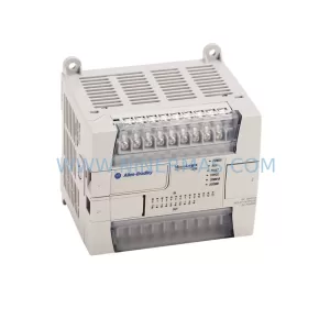
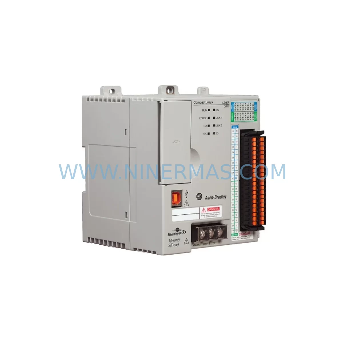
Allen-Bradley 1769-L24ER-QBFCIB Retrofit Controller for Legacy Systems
Verify the part, confirm the platform family, and move straight into quotation with the right commercial details.
RFQ Ready
- SKU1769-L24ER-QBFCIB
- CategoryPLC & Industrial Automation Modules
- BrandAllen-Bradley
- SupportAvailability, lead time, condition, and shipping coordination
How Buyers Usually Use This Page
- Confirm the exact part number and platform family before sending the quote request.
- Use direct email when quantity, condition, and destination are already defined internally.
- Switch to the broader brand or category archive when you need alternates nearby.
Series Navigation
Move through the most common platform families behind this part.
Product RFQ
Send this part directly for quotation.
Include quantity, required condition, destination country, and target delivery timing. Current reference: Allen-Bradley 1769-L24ER-QBFCIB Retrofit Controller for Legacy Systems with SKU 1769-L24ER-QBFCIB.
Allen-Bradley 1769-L24ER-QBFCIB Retrofit Controller for Legacy Systems
The Allen-Bradley 1769-L24ER-QBFCIB is a CompactLogix 5370 L2 controller engineered for seamless integration into existing 1769-series control architectures. As legacy SLC 500, MicroLogix 1500, and early CompactLogix L20 platforms reach end-of-life, the 1769-L24ER-QBFCIB provides a validated migration path that preserves existing I/O wiring, minimises rack reconfiguration, and protects original ladder logic investments. With dual EtherNet/IP ports, 512 KB of user memory, and native support for the 1769 Compact I/O bus, this controller is the preferred retrofit choice for plant engineers managing ageing control cabinets across discrete manufacturing, material handling, and process automation environments.
When planning a retrofit around the 1769-L24ER-QBFCIB, engineers must verify several critical compatibility parameters before committing to a cutover window. Power supply capacity is the first checkpoint: the 1769-PA2 or 1769-PB2 power supply must be confirmed against the total current draw of all installed 1769 I/O modules on the local bus. Terminal wiring on existing 1769-IQ16 digital input modules and 1769-OB16 digital output modules is fully compatible with the L24ER-QBFCIB backplane interface, eliminating the need to re-terminate field cables. Backplane slot addressing must be re-validated in Studio 5000 Logix Designer after the controller swap, particularly where 1769-IF4 analogue input modules or 1769-OF2 analogue output modules occupy non-default slot positions. Module addressing errors are the most common source of post-retrofit faults and should be resolved during bench testing before the unit is installed in the live cabinet.
Program compatibility between the legacy controller and the 1769-L24ER-QBFCIB is generally high when migrating from CompactLogix L20 or L23 platforms, but RSLogix 5000 project files must be converted to Studio 5000 format and re-compiled against the L24ER firmware revision. Tag-based addressing is preserved, and existing HMI screens built on PanelView Plus 6 or PanelView Plus 7 terminals typically require only a controller path update rather than a full screen rebuild. EtherNet/IP communication links to upstream SCADA systems, historian servers, or MES platforms should be re-tested after the controller replacement to confirm that implicit messaging connections and explicit CIP reads are re-established within the expected timeout windows.
For control cabinets that also house a 1769-L16ER-BB1B or 1769-L18ER-BB1B as a secondary controller, the 1769-L24ER-QBFCIB can be installed in the same DIN-rail footprint without mechanical modification. Where the existing rack includes a 1769-SDN DeviceNet scanner module for legacy field device communication, the scanner configuration file must be exported and re-imported after the controller swap to maintain device node assignments. Similarly, if a 1769-ASCII serial communication module is present for legacy barcode reader or weighing terminal integration, the ASCII driver configuration must be verified against the new controller’s serial port settings.
Installation space confirmation is a mandatory pre-retrofit step. The 1769-L24ER-QBFCIB occupies a standard 1769 end-cap slot position and requires a minimum 50 mm clearance above and below the module for adequate airflow. Cabinet thermal surveys should be conducted if the existing enclosure was sized for an older, lower-dissipation controller. On-site commissioning should include a full I/O force test, a communications link verification across all EtherNet/IP nodes, and a controlled power-cycle sequence to confirm that the controller reaches RUN mode without faults. Shipment testing at NINERMAS includes a functional power-on test and firmware version verification before dispatch.
Upgrade Compatibility Table
| Parameter | Legacy Platform | 1769-L24ER-QBFCIB | Retrofit Note |
|---|---|---|---|
| Controller Series | CompactLogix L20 / L23 / SLC 500 | CompactLogix 5370 L2 | Direct series upgrade; same 1769 bus |
| Backplane Interface | 1769 Compact I/O Bus | 1769 Compact I/O Bus | Fully compatible; no rewiring required |
| Communication Ports | Single EtherNet/IP or RS-232 | Dual EtherNet/IP (embedded switch) | Linear/DLR topology supported natively |
| Programming Software | RSLogix 5000 v16–v20 | Studio 5000 Logix Designer v21+ | Project conversion required; tags preserved |
| User Memory | 128–256 KB (L20/L23) | 512 KB | Expanded capacity; no program truncation |
| I/O Module Compatibility | 1769-IQ16, OB16, IF4, OF2, etc. | All 1769 Compact I/O modules | Slot addressing must be re-validated |
| HMI Compatibility | PanelView Plus 6 / Plus 7 | PanelView Plus 6 / Plus 7 / Plus 7 Performance | Controller path update only; no screen rebuild |
| Power Supply | 1769-PA2 / 1769-PB2 | 1769-PA2 / 1769-PB2 | Verify total bus current draw before cutover |
| Installation Footprint | Standard 1769 end-cap position | Standard 1769 end-cap position | No mechanical modification required |
| Warranty | OEM warranty expired (EOL) | 12-Month Warranty (NINERMAS) | Covers functional defects from date of shipment |
Retrofit Planning for Existing Automation Systems
A successful retrofit centred on the 1769-L24ER-QBFCIB begins with a comprehensive audit of the existing control cabinet. Engineers should document every module installed on the 1769 local bus, including digital I/O modules such as the 1769-IQ16 and 1769-OB16, analogue modules such as the 1769-IF4 and 1769-OF2, and any specialty modules such as the 1769-HSC high-speed counter or 1769-SM2 motion module. Each module’s slot number, I/O tag mapping, and wiring termination must be recorded before the legacy controller is removed.
The 1769-PA2 power supply should be load-tested against the combined current draw of all installed modules. If the existing power supply is operating near its rated output, a second 1769-PA2 or an upgraded 1769-PB2 DC power supply should be provisioned before the cutover date. Signal isolation requirements should also be reviewed: where legacy analogue loops interface with third-party transmitters or positioners, a 1769-IF4 with appropriate signal conditioning or an external signal isolator may be required to maintain loop integrity after the controller swap.
Communication infrastructure planning is equally critical. The 1769-L24ER-QBFCIB’s dual EtherNet/IP ports support Device Level Ring (DLR) topology, enabling a resilient network architecture that eliminates single points of failure on the plant floor network. Where legacy systems relied on a 1769-SDN DeviceNet scanner for field device communication, a migration path to EtherNet/IP-native devices or a retained DeviceNet scanner configuration must be planned. Serial communication links using a 1769-ASCII module for legacy peripheral integration should be tested for baud rate and framing compatibility with the new controller’s serial driver.
For multi-axis motion applications, the 1769-L24ER-QBFCIB supports Integrated Motion on EtherNet/IP, enabling direct replacement of legacy pulse-train motion architectures with CIP Motion-compatible servo drives. Where the existing system uses a 1769-SM2 stepper/servo module, a transition to an EtherNet/IP-based Kinetix 5500 or Kinetix 5700 drive should be evaluated as part of the broader retrofit scope. Programming cables such as the 1784-U2DHP USB-to-DH+ adapter may be required during the transition period if legacy devices on the same network still require DH+ communication for firmware updates or diagnostics.
Downtime Control During System Migration
Minimising production downtime is the primary operational constraint in any legacy PLC retrofit. For the 1769-L24ER-QBFCIB migration, a structured cutover plan should be developed at least four weeks before the scheduled maintenance window. The plan must include a full backup of the existing controller program in RSLogix 5000 or Studio 5000 format, a verified copy of all HMI screen files from the PanelView Plus terminal, and a documented snapshot of all EtherNet/IP device configurations including IP addresses, connection parameters, and RPI settings.
Bench testing the 1769-L24ER-QBFCIB with a representative subset of the production I/O configuration before the live cutover is strongly recommended. This allows engineers to validate the converted Studio 5000 project, confirm that all I/O tags resolve correctly, and verify that HMI communications are re-established without manual intervention. Where the production process cannot tolerate an extended outage, a parallel-run strategy using the new controller in Program mode alongside the live legacy controller allows final validation without interrupting production.
During the physical cutover, the sequence should follow a defined order: power down the cabinet, remove the legacy controller, install the 1769-L24ER-QBFCIB in the end-cap position, restore power, download the validated program, and perform a controlled I/O force test before releasing the system to automatic mode. Post-cutover monitoring for the first 24 hours should include logging of all controller faults, EtherNet/IP connection status, and analogue loop readings to confirm that the retrofit has not introduced any signal integrity issues. NINERMAS supplies each 1769-L24ER-QBFCIB with a functional power-on test certificate and a 12-month warranty covering all operational defects from the date of shipment, providing additional assurance during the post-retrofit stabilisation period.
Retrofit Support FAQ
Q1: Is the 1769-L24ER-QBFCIB a direct drop-in replacement for the 1769-L20ER-BB1B or 1769-L23E-QB1B?
The 1769-L24ER-QBFCIB occupies the same end-cap slot position and uses the same 1769 Compact I/O backplane interface as the L20ER and L23E controllers, making it mechanically and electrically compatible. The primary differences are expanded user memory (512 KB vs. 128–256 KB), dual EtherNet/IP ports, and a firmware baseline requiring Studio 5000 Logix Designer v21 or later. The existing RSLogix 5000 project must be converted and re-compiled, but all tag definitions and ladder logic structures are preserved during the conversion process.
Q2: What wiring changes are required when replacing a legacy controller with the 1769-L24ER-QBFCIB?
No field wiring changes are required for 1769 Compact I/O modules already installed on the local bus. Terminal block wiring on modules such as the 1769-IQ16, 1769-OB16, 1769-IF4, and 1769-OF2 remains unchanged. The only wiring task is connecting the EtherNet/IP network cables to the controller’s dual RJ-45 ports and confirming that the power supply connections to the 1769-PA2 or 1769-PB2 are secure. If the legacy controller used an RS-232 serial port for HMI or peripheral communication, the serial cable must be re-routed to the L24ER-QBFCIB’s RS-232 port and the driver settings re-confirmed.
Q3: How does NINERMAS verify the 1769-L24ER-QBFCIB before shipment, and what does the 12-month warranty cover?
Every 1769-L24ER-QBFCIB unit supplied by NINERMAS undergoes a functional power-on test, firmware version verification, and EtherNet/IP port continuity check before dispatch. The 12-month warranty covers all functional defects arising from manufacturing or component failure under normal operating conditions. It does not cover damage resulting from incorrect installation, overvoltage events, or environmental exposure beyond the module’s rated specifications. Warranty claims are processed directly through NINERMAS with a target response time of two business days.
Q4: Can the 1769-L24ER-QBFCIB be used in a DLR (Device Level Ring) EtherNet/IP topology?
Yes. The 1769-L24ER-QBFCIB’s embedded dual-port EtherNet/IP switch natively supports DLR topology, providing automatic network fault recovery without requiring an external managed switch. This makes it suitable for retrofit projects where network resilience is a requirement, such as continuous process lines or safety-critical material handling systems. Existing linear EtherNet/IP topologies can be migrated to DLR incrementally without replacing field devices, as DLR is backward-compatible with standard EtherNet/IP linear connections.
| Product Series | CompactLogix |
|---|---|
| Country of Origin | US |
Catalog Continuation
More Allen-Bradley modules in the catalog.
Use the brand lane to compare nearby part numbers, platform-adjacent modules, and other inquiry-ready listings before sending your final RFQ.
Catalog Continuation
Alternative parts within PLC & Industrial Automation Modules.
Stay inside the same system family when you need substitutes, adjacent modules, or a broader shortlist for procurement review.
SKU: OZDPROFI12MG12
Hirschmann OZDPROFI12MG12 Spare Part for Industrial Maintenance
SKU: 07025-0000-70-1-04
KONTRON 07025-0000-70-1-04 Service-Ready Spare Part