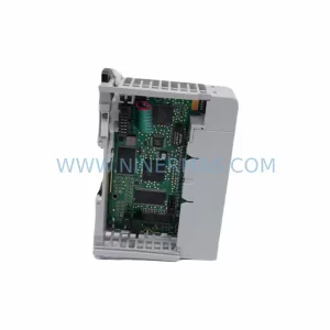
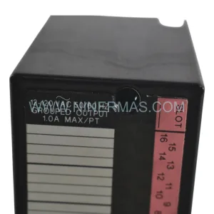
Original Industrial Spare Part
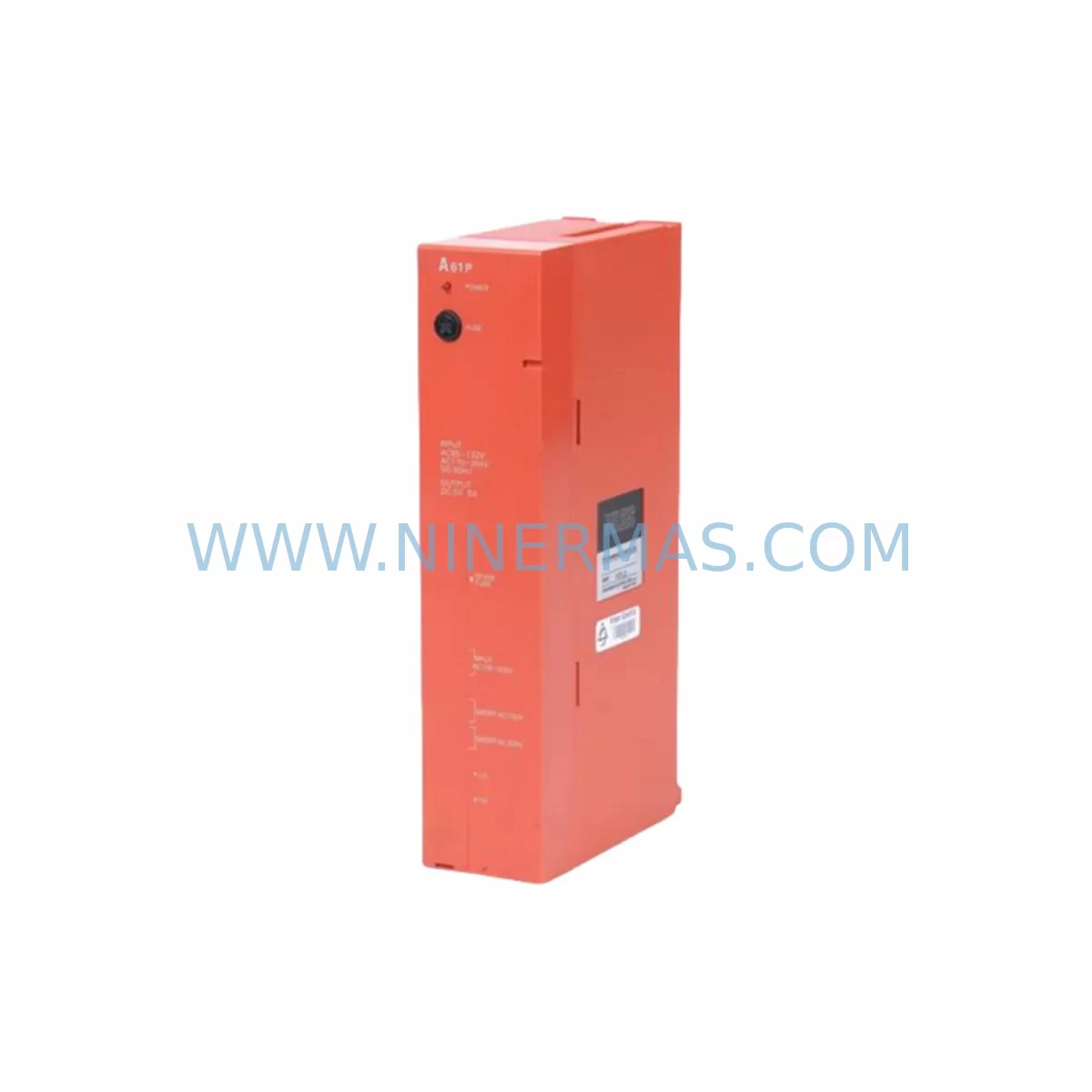
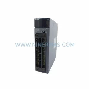
Mitsubishi A61P Retrofit-Compatible Power Supply for Legacy Systems
Verify the part, confirm the platform family, and move straight into quotation with the right commercial details.
RFQ Ready
- SKUA61P
- CategoryPLC & Industrial Automation Modules
- BrandMitsubishi
- SupportAvailability, lead time, condition, and shipping coordination
How Buyers Usually Use This Page
- Confirm the exact part number and platform family before sending the quote request.
- Use direct email when quantity, condition, and destination are already defined internally.
- Switch to the broader brand or category archive when you need alternates nearby.
Series Navigation
Move through the most common platform families behind this part.
Product RFQ
Send this part directly for quotation.
Include quantity, required condition, destination country, and target delivery timing. Current reference: Mitsubishi A61P Retrofit-Compatible Power Supply for Legacy Systems with SKU A61P.
Mitsubishi A61P Retrofit-Compatible Power Supply for Legacy Systems
The Mitsubishi A61P is a DC power supply module designed for the MELSEC-A series programmable logic controller platform — one of the most widely deployed legacy automation architectures in discrete manufacturing, process control, and infrastructure applications across Asia-Pacific, Europe, and the Americas. As Mitsubishi Electric has progressively phased out the A-series product line in favour of the Q-series and iQ-R series platforms, the A61P has become a critical retrofit and replacement component for facilities that continue to operate legacy A-series control panels and cannot justify a full system migration at this time.
For maintenance engineers and automation integrators managing ageing control infrastructure, sourcing a verified, tested A61P is often the difference between a controlled, planned upgrade and an unplanned production shutdown. NINERMAS maintains stock of the A61P to support exactly these scenarios — providing a reliable supply chain bridge while customers plan their longer-term migration strategy.
Upgrade Compatibility Table
| Parameter | A61P Specification | Retrofit / Replacement Notes |
|---|---|---|
| Compatible Backplane | A-series main base units (A32B, A52B, A62B, A68B) | Verify slot position and base unit revision before installation |
| Output Voltage | 5 VDC, 24 VDC auxiliary | Confirm downstream I/O module voltage requirements match |
| Input Voltage Range | 100–240 VAC, 50/60 Hz | Check panel supply voltage and circuit breaker rating |
| Communication Compatibility | MELSEC-A bus (A-bus) | Not directly compatible with Q-series or iQ-R backplanes without adapter |
| Physical Dimensions | Standard A-series PSU form factor | Confirm cabinet rail space and module slot clearance |
| Replacement Path | Direct drop-in for A61P units | For Q-series migration, consider Q61P or Q62P with base unit change |
| Commissioning | No parameter configuration required | Verify LED status indicators post-installation; check ERR output signal |
| Warranty | 12-Month Warranty — all units tested prior to shipment | |
Retrofit Planning for Existing Automation Systems
When integrating the A61P into an existing or partially upgraded control system, a structured retrofit plan significantly reduces risk and commissioning time. The first step is a full panel audit: document the existing A-series base unit model (commonly the A32B, A52B, or A62B), the installed CPU module (such as the A2USCPU, A3UCPU, or A2ACPU), and all I/O modules currently occupying the rack slots. This baseline inventory is essential before any hardware is disturbed.
Power capacity is a frequent oversight in A-series retrofits. The A61P supplies 5 VDC at a rated current that must cover the combined load of the CPU, all installed I/O modules, and any special function modules such as the A1SD61 high-speed counter module or A1SJ71UC24-R4 serial communication module. If the existing system has been expanded over time with additional modules, recalculate the total current draw against the A61P’s rated output before assuming a direct swap is sufficient.
Terminal wiring on the A61P follows the standard A-series PSU layout. Before disconnecting the existing unit, photograph or document all wiring connections, particularly the AC input terminals, the 24 VDC auxiliary output connections, and the ERR contact output wiring used for external alarm circuits. Incorrect rewiring of the ERR output is a common commissioning error that can mask fault conditions during initial power-up.
For systems that include an A1SJ71QBR11 MELSECNET/B remote I/O master module or an A1SJ71E71-B5 Ethernet interface module, verify that the communication links are re-established correctly after the power supply replacement. These modules rely on stable 5 VDC backplane power, and any marginal supply voltage can cause intermittent communication faults that are difficult to diagnose without a power quality measurement at the backplane connector.
HMI connectivity is another area requiring attention. If the control system interfaces with a GOT1000 series HMI (such as the GT1575-VNBA) via RS-422 or the A-bus direct connection, confirm that the HMI screen data and tag addresses remain valid after the power cycle. In some installations, HMI internal clock data or recipe parameters stored in volatile memory may need to be reloaded following an extended power interruption during the swap procedure.
Where the retrofit scope extends beyond a simple power supply replacement — for example, when simultaneously upgrading from an A2ACPU to a Q02UCPU as part of a phased Q-series migration — the A61P serves as a stabilising element for the remaining A-series I/O infrastructure during the transition period. In these hybrid configurations, the A-series rack continues to operate under A61P power while the new Q-series CPU communicates with legacy I/O via an AJ65BT-64AD analog input module or similar A/Q bridge component.
Downtime Control During System Migration
Minimising production downtime during a power supply replacement or broader system migration requires preparation that begins well before the maintenance window. For the A61P specifically, the replacement procedure itself is straightforward — the module is a plug-in unit with no internal adjustments — but the surrounding activities determine whether the changeover takes 30 minutes or 3 hours.
Prior to the maintenance window, back up the CPU program using GX Developer or GX Works2 connected via the A-series programming cable (SC-09 or USB-SC09-A adapter). Confirm that the backup file opens correctly and that the program version matches the currently running logic. Store the backup on at least two independent media. If the system uses latched data registers or file registers (ZR device), ensure these are also captured, as they may not be retained through a cold restart depending on the battery backup status of the A2USCPU or equivalent CPU module.
During the swap, work with the process team to place the controlled system in a safe hold state before isolating the panel supply. After installing the A61P and restoring power, observe the module’s POWER LED and confirm the CPU RUN LED returns to normal status before releasing the process. Check the ERR LED and any external alarm outputs before declaring the system operational. A brief functional test of critical I/O points — particularly safety interlocks and process control outputs — should be completed before handing back to operations.
For facilities with redundant control architectures, coordinate the A61P replacement with the redundancy switchover procedure to maintain continuous process control throughout the maintenance activity.
Retrofit Support FAQ
Q: Is the A61P a direct replacement for all A-series power supply variants?
A: The A61P is compatible with standard A-series base units including the A32B, A52B, A62B, and A68B. It is not interchangeable with the A61PN (which accepts a different input voltage range) or with Q-series base units. Always verify the base unit model and existing PSU part number before ordering.
Q: What pre-shipment testing is performed on A61P units?
A: All A61P units supplied by NINERMAS are functionally tested for output voltage accuracy, load regulation, and ERR contact operation prior to dispatch. Units are supplied with a 12-month warranty covering defects in materials and workmanship under normal operating conditions.
Q: Can the A61P be used during a phased migration to the Q-series platform?
A: Yes. The A61P can continue to power the existing A-series rack while Q-series hardware is introduced in parallel. This approach is common in phased migrations where full cutover is not immediately feasible. Consult your system integrator regarding the appropriate A/Q bridge modules for your specific I/O configuration.
Q: What is the typical lead time and stock availability?
A: NINERMAS maintains inventory of the A61P to support urgent replacement requirements. Standard orders are processed and dispatched within 1–3 business days. Contact our team for current stock levels and expedited shipping options.
| Product Series | MELSEC-A |
|---|---|
| Country of Origin | JP |
Catalog Continuation
More Mitsubishi modules in the catalog.
Use the brand lane to compare nearby part numbers, platform-adjacent modules, and other inquiry-ready listings before sending your final RFQ.
Catalog Continuation
Alternative parts within PLC & Industrial Automation Modules.
Stay inside the same system family when you need substitutes, adjacent modules, or a broader shortlist for procurement review.
SKU: 16-167627-00 8122 410 05002, 4022.470.78191 8122 410 55702 16-273491-00
Novellus 16-167627-00 Service-Ready Industrial Spare Part
SKU: 2305451-C DT2000 0626 P2, OLE36-10632-02
Advanced Energy 2305451-C Service-Ready Industrial Spare Part