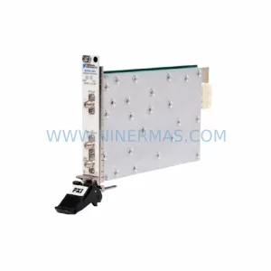
Original Industrial Spare Part
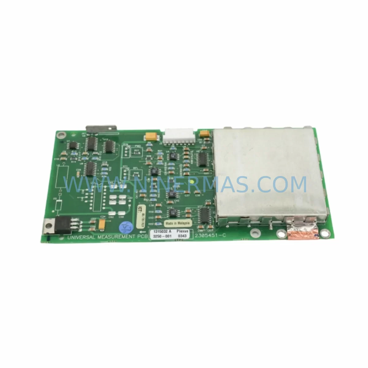
Advanced Energy 2305451-C Service-Ready Industrial Spare Part
Verify the part, confirm the platform family, and move straight into quotation with the right commercial details.
RFQ Ready
- SKU2305451-C DT2000 0626 P2, OLE36-10632-02
- CategoryPLC & Industrial Automation Modules
- BrandAdvanced Energy
- SupportAvailability, lead time, condition, and shipping coordination
How Buyers Usually Use This Page
- Confirm the exact part number and platform family before sending the quote request.
- Use direct email when quantity, condition, and destination are already defined internally.
- Switch to the broader brand or category archive when you need alternates nearby.
Series Navigation
Move through the most common platform families behind this part.
Product RFQ
Send this part directly for quotation.
Include quantity, required condition, destination country, and target delivery timing. Current reference: Advanced Energy 2305451-C Service-Ready Industrial Spare Part with SKU 2305451-C DT2000 0626 P2, OLE36-10632-02.
Advanced Energy 2305451-C Service-Ready Industrial Spare Part: Spare Replacement and Downtime Risk Control
The Advanced Energy 2305451-C is a service-ready spare part designed for the DT2000 series DC power supply and plasma power platform. Engineered for demanding industrial environments, this component supports continuous operation in semiconductor fabrication, flat panel display manufacturing, solar cell production, and general industrial plasma processing systems. Maintaining a verified stock of the 2305451-C in your spare parts inventory is a proven strategy for minimizing unplanned downtime and protecting production continuity.
Advanced Energy’s DT2000 platform — including variants such as the DT2000-0626-P2 and associated sub-assemblies like the OLE36-10632-02 control board — is widely deployed across legacy and active production lines globally. As these systems age, sourcing original replacement modules becomes increasingly critical. The 2305451-C is a direct-fit, original-specification spare that eliminates the compatibility risk associated with aftermarket substitutes.
Spare Maintenance Table
| Parameter | Specification / Detail |
|---|---|
| Part Number | 2305451-C |
| Series | Advanced Energy DT2000 |
| Related Model | DT2000-0626-P2 / OLE36-10632-02 |
| Component Type | DC Power Supply Module / Control Sub-Assembly |
| Application | Plasma Processing, Semiconductor Fab, Industrial DC Power Systems |
| Input Voltage Range | Per DT2000 platform specification (typically 200–480 VAC, 3-phase) |
| Output | Regulated DC output per DT2000 configuration |
| Cooling | Forced air / internal fan assembly (verify fan module condition at replacement) |
| Mounting | Rack / chassis-integrated per DT2000 enclosure standard |
| Operating Temperature | 0°C to 50°C (verify site ambient conditions) |
| Compatibility | Advanced Energy DT2000 series; verify firmware and hardware revision before installation |
| Condition | Original spare, pre-shipment tested |
| Warranty | 12 Months from date of shipment |
| Lead Time | Contact for current stock availability |
| Origin | United States (Advanced Energy Industries) |
Maintenance Planning for Continuous Operation
When replacing the Advanced Energy 2305451-C in a DT2000-series power system, a disciplined maintenance engineer will treat the replacement as an opportunity for a broader cabinet inspection. The DT2000 platform integrates multiple interdependent sub-systems, and a failure in the 2305451-C module is frequently accompanied by stress on adjacent components.
Begin by inspecting the DT2000 internal fan assembly and cooling airflow path. Thermal stress is the leading cause of premature module failure in plasma power systems, and a degraded fan module will shorten the service life of any replacement part. Alongside the fan, check the DC bus capacitor bank for signs of bulging, leakage, or elevated ESR — capacitor degradation is a common co-failure mode in aging DT2000 units.
Next, verify the condition of the OLE36-10632-02 control board and its associated fiber optic communication links. The DT2000 platform uses fiber optic cables for noise-immune communication between the power stage and the system controller; inspect connectors for contamination or physical damage and replace any degraded fiber optic patch cables as a precaution.
On the input side, inspect the three-phase input fuse assembly and the EMI filter module. A blown or weakened fuse is often a symptom of upstream surge events that may have also stressed the 2305451-C. The EMI filter should be checked for continuity and insulation integrity, particularly in environments with frequent arc events or heavy motor loads on the same bus.
For systems integrated with a PLC or DCS controller — such as a Siemens S7-300/400 series or an Allen-Bradley ControlLogix rack — verify that the analog I/O module providing setpoint signals to the DT2000 is operating within calibrated range. A drifting analog output card can cause the power supply to operate outside its design envelope, accelerating wear on internal modules including the 2305451-C.
If the DT2000 is controlled via a DeviceNet or Profibus communication module, inspect the network termination resistors and cable shielding. Communication faults can trigger protective shutdowns that mask the true root cause of a module failure. Similarly, check the HMI panel (if present) for alarm history that may reveal intermittent fault patterns preceding the failure.
Finally, review the condition of the terminal block wiring on the output side. Loose or corroded terminals on high-current DC output connections generate localized heat that can propagate back into the power module. Torque all terminals to specification and apply anti-oxidant compound where appropriate for the installation environment.
Procurement engineers sourcing the 2305451-C for annual maintenance kits should also consider stocking the Advanced Energy 2305451-A and 2305451-B variants as cross-reference spares, as well as compatible modules from the Advanced Energy Pinnacle series for sites planning a phased upgrade of legacy DT2000 installations.
Site Replacement Workflow
Step 1 — Isolation and Lockout/Tagout: De-energize the DT2000 system following site LOTO procedures. Discharge the DC bus capacitors and verify zero voltage with a calibrated meter before opening the enclosure.
Step 2 — Documentation: Photograph the existing wiring, connector positions, and module orientation before removal. Record the hardware revision label on the outgoing 2305451-C for traceability.
Step 3 — Module Removal: Disconnect fiber optic cables, signal connectors, and power terminals in the sequence specified in the DT2000 service manual. Remove the module using ESD-safe handling procedures.
Step 4 — Inspection and Cleaning: Clean the module bay, inspect the backplane connector for bent pins or contamination, and verify that the replacement 2305451-C hardware revision is compatible with the installed firmware version.
Step 5 — Installation and Verification: Install the replacement module, reconnect all cables and terminals, and restore power. Perform a controlled power-on sequence and verify output parameters against the process recipe setpoints before returning the system to production.
Step 6 — Functional Test: Run the system through a representative process cycle and monitor for fault codes, thermal alarms, or output instability. Log the replacement in the site maintenance management system (CMMS) with the new module serial number and warranty start date.
This structured workflow reduces mean time to repair (MTTR), ensures system compatibility, and provides the documentation trail required for warranty claims and regulatory audits.
Spare Parts Support FAQ
Q1: Is the 2305451-C a new original part or a refurbished unit?
All units supplied by NINERMAS are original Advanced Energy spare parts, pre-shipment tested to verify electrical performance against factory specifications. Each unit ships with a 12-month warranty from the date of shipment. Refurbished or aftermarket substitutes are not offered.
Q2: How do I confirm compatibility with my specific DT2000 configuration?
Compatibility depends on the DT2000 hardware revision and installed firmware version. Please provide your full system model number (e.g., DT2000-0626-P2), the existing module part number, and the hardware revision label when enquiring. Our technical team will confirm fit before shipment.
Q3: What is the recommended inventory strategy for the 2305451-C?
For production-critical systems, we recommend maintaining a minimum of one 2305451-C on-site as a hot spare, particularly for DT2000 units that have been in service for more than five years. For multi-tool facilities, a shared pool of two to three units is a cost-effective approach that balances carrying cost against downtime risk. Long-term supply agreements are available for customers requiring guaranteed stock over a 12–36 month horizon.
Q4: What does the 12-month warranty cover, and how is a claim initiated?
The 12-month warranty covers defects in materials and workmanship under normal operating conditions. It does not cover damage resulting from incorrect installation, overvoltage events, or operation outside the specified environmental range. To initiate a warranty claim, contact sale@ninermas.com with the original invoice number, the unit serial number, and a description of the fault. NINERMAS will arrange return logistics and provide a replacement or repair within the agreed service timeline.
| Product Series | Other series |
|---|
Catalog Continuation
More Advanced Energy modules in the catalog.
Use the brand lane to compare nearby part numbers, platform-adjacent modules, and other inquiry-ready listings before sending your final RFQ.
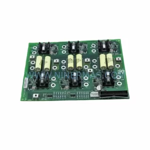
SKU: 2301350-A 90157017 173733-001 TTLD13-11 FIMS-F 3881-020024-12
Advanced Energy 2301350-A Service-Ready Spare for Maintenance
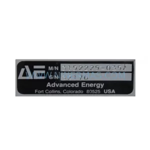
SKU: 3152225-035A MDX-10K AP1415S 2PW MVE4 MVE4 P 23020202-B
Advanced Energy 3152225-035A Retrofit-Compatible RF Generator
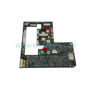
SKU: RFG 3000 V2 2305198-A 80DI96DO 8A02AI 810-013872-002 SCU-STC-G
Advanced Energy 810-013872-002 Safety-Reliable RF Power Supply
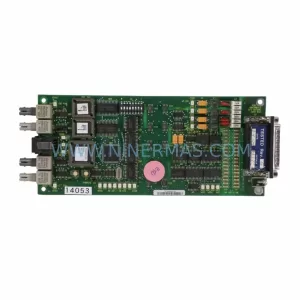
SKU: CEX, RFG 1250 2305155-A RFG1250 2305107-B 2305145-C
Advanced Energy CEX-RFG-1250 Service-Ready Industrial Spare Part
Catalog Continuation
Alternative parts within PLC & Industrial Automation Modules.
Stay inside the same system family when you need substitutes, adjacent modules, or a broader shortlist for procurement review.
SKU: 16-167627-00 8122 410 05002, 4022.470.78191 8122 410 55702 16-273491-00
Novellus 16-167627-00 Service-Ready Industrial Spare Part