Description
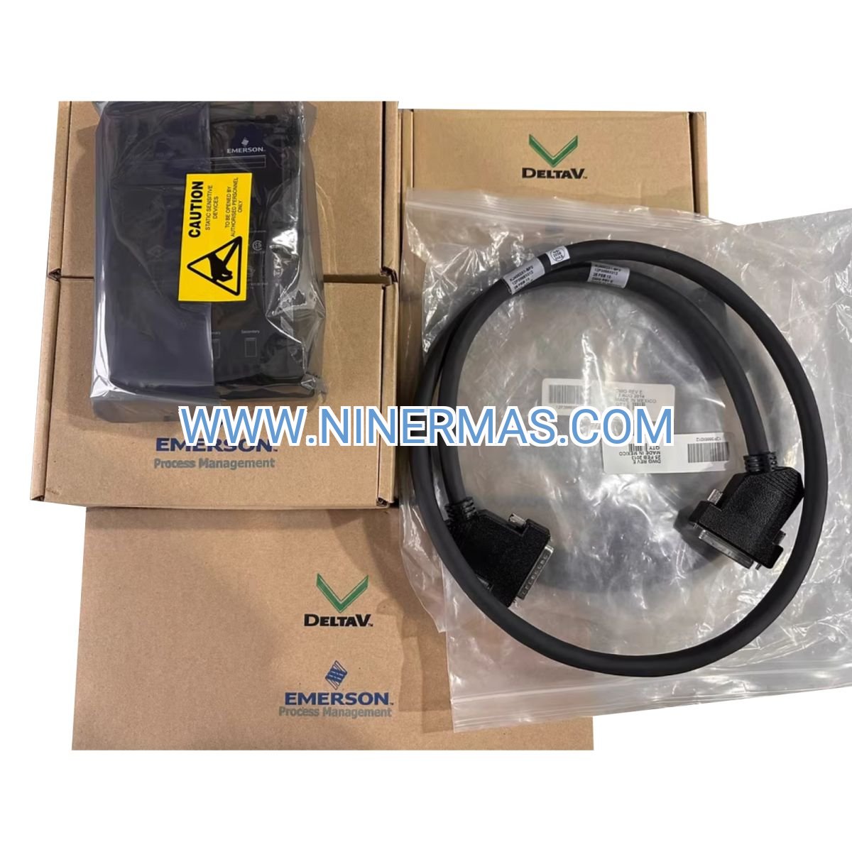
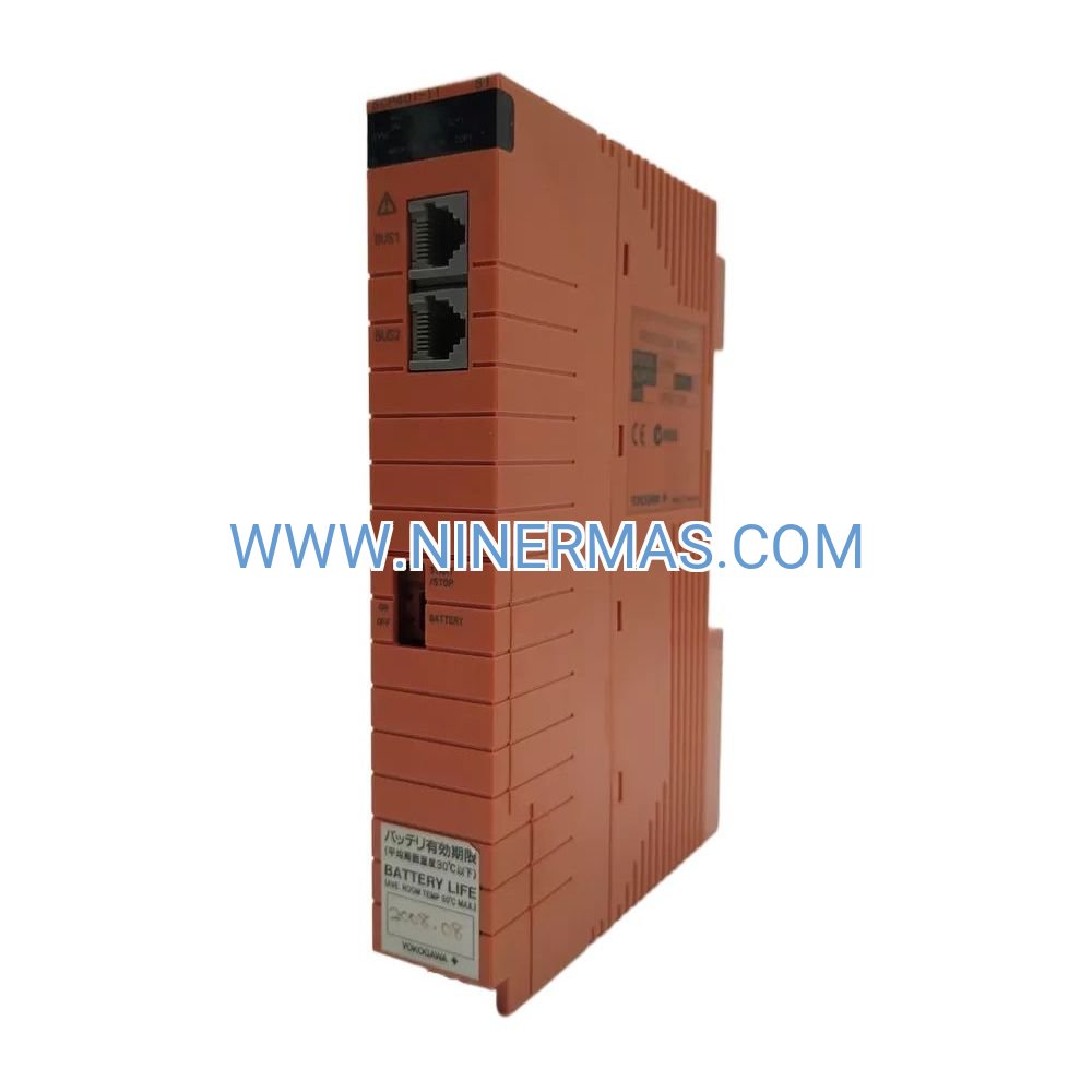
KJ4002X1-BE1 Top Extender Cable Assembly – Industrial-Grade DeltaV Vertical Expansion Solution
Expand your DeltaV distributed control system upward with the Emerson KJ4002X1-BE1 Top Extender Cable Assembly, engineered for vertical I/O carrier mounting in space-constrained control cabinets. This industrial-grade LocalBus interconnect delivers 12.6VDC power at 15A capacity alongside high-speed digital communication, enabling reliable upward expansion in oil refineries, chemical plants, pharmaceutical facilities, and power generation installations where floor space is limited but vertical clearance is available.
Why Choose Upward I/O Expansion?
Traditional bottom-mount expansion consumes valuable lower cabinet space needed for cable routing and future additions. The KJ4002X1-BE1 top extender solves this challenge by enabling upward vertical growth, preserving lower cabinet zones for field wiring terminations while maximizing total I/O density per cabinet footprint. This configuration is particularly valuable during retrofit projects where existing installations block conventional downward expansion paths.
Process engineers and system integrators select top extenders when phased capacity additions require preserving existing layouts, when multi-level control rooms demand vertical LocalBus routing between floors, or when organizing I/O carriers by functional area within tall marshalling cabinets improves operational efficiency and maintenance accessibility.
Key Features & Industrial Benefits
- → Integrated Power & Communication: Single cable assembly eliminates separate power and data wiring, reducing installation time by 40% compared to discrete cable runs while improving system reliability through factory-tested connections
- ✓ Global Hazardous Area Approvals: FM/CSA Class I Division 2 Groups A-D, ATEX Zone 2, IECEx certified, plus DNV/ABS marine approvals enable deployment in explosive atmospheres worldwide without additional certification costs or engineering delays
- → Extended Environmental Range: -40°C to +70°C operating temperature with ISA-S71.04 Class G3 conformal coating protects against corrosive industrial atmospheres, extreme climates, and harsh process environments from Arctic installations to tropical refineries
- ✓ Scalable Architecture: Supports incremental I/O additions without controller upgrades or system downtime, enabling phased plant expansions that align capital expenditure with production growth while maintaining operational continuity
- → Simplified Compliance: Pre-assembled factory configuration eliminates field termination errors that cause 60% of commissioning delays, accelerating project schedules and reducing installation labor costs by up to 30%
- ✓ Bidirectional Expansion Flexibility: Combine with bottom extenders (BF-series) for maximum cabinet utilization, creating custom I/O layouts that optimize accessibility, cable management, and functional organization
Application Scenarios Across Industries
Refinery Control Room Retrofits
When expanding crude distillation unit monitoring capacity, existing DCS cabinets often have limited floor space but available vertical clearance. The KJ4002X1-BE1 enables adding new temperature, pressure, and flow I/O carriers above current installations without relocating equipment or adding cabinets. This approach reduces project costs by 25-35% compared to new cabinet installations while maintaining existing cable routing infrastructure and minimizing turnaround duration.
Pharmaceutical Batch System Expansions
GMP-regulated facilities require segregated I/O for different production suites to maintain batch traceability and prevent cross-contamination. Top extenders allow organizing I/O carriers vertically by production area within validated control systems, placing critical process parameters at eye level for operator verification while positioning less frequently accessed utility I/O in upper cabinet positions. This configuration improves audit readiness and reduces validation documentation complexity.
Chemical Plant Phased Capacity Additions
During multi-year plant expansions, process units come online sequentially. Top extenders support adding new reactor, separator, and storage tank I/O incrementally without disrupting operational systems. Engineers can commission new I/O carriers during scheduled maintenance windows, connecting them to existing LocalBus infrastructure without hot work permits or extended production shutdowns, accelerating time-to-revenue for new capacity.
Power Generation Turbine Control Upgrades
When retrofitting legacy turbine control systems with modern DeltaV I/O, physical constraints around existing equipment limit expansion options. Top extenders provide alternative routing paths when bottom-mount configurations conflict with cable trays, conduit runs, or structural supports. This flexibility reduces engineering rework and enables optimal I/O placement relative to field devices, minimizing wire run lengths and installation costs.
Offshore Platform Space Optimization
Marine installations face severe space constraints where every cubic meter of control room volume carries premium value. Vertical I/O expansion maximizes cabinet density, reducing total cabinet count and associated HVAC, fire suppression, and structural support costs. DNV/ABS certification ensures compliance with maritime safety standards while top-mount configuration simplifies maintenance access in confined offshore environments.
Technical Specifications & Selection Guide
| Parameter | Specification | Engineering Notes |
|---|---|---|
| Model Number | KJ4002X1-BE1 | Top extender configuration for upward expansion |
| LocalBus Power | 12.6VDC @ 15A maximum | Calculate total I/O module consumption to avoid overload |
| Operating Temperature | -40°C to +70°C | Suitable for extreme climate installations |
| Maximum System Length | 6.5 meters total | Sum of all carriers + extender cables in LocalBus chain |
| Shock Resistance | 10g ½-sinewave, 11ms | Withstands transportation and installation handling |
| Vibration Tolerance | 1mm p-p (5-16Hz); 0.5g (16-150Hz) | Suitable for installations near rotating equipment |
| Humidity Range | 5% to 95% non-condensing | Requires climate-controlled environment |
| Enclosure Rating | IP20 | Control room installation only |
| Corrosion Protection | ISA-S71.04-1985 Class G3 | Conformal coating for industrial atmospheres |
Top vs. Bottom Extender Selection Criteria
Choose the optimal expansion direction based on your specific installation requirements:
Select Top Extender (KJ4002X1-BE1) when:
- • Lower cabinet space is reserved for future field wiring terminations
- • Existing bottom-mount equipment blocks downward expansion
- • Vertical clearance exceeds 2 meters above current installation
- • Organizing I/O by elevation improves operational accessibility
- • Retrofit projects require preserving existing cable routing
Select Bottom Extender (BF-series) when:
- • Gravity-assisted cable routing simplifies installation
- • Lower cabinet positions improve maintenance access
- • Conventional downward expansion aligns with existing architecture
- • Field termination access is prioritized over vertical space
Advanced System Integration Capabilities
Hybrid Expansion Architectures: Combine top and bottom extenders within the same LocalBus chain to create custom I/O layouts that optimize both vertical space utilization and functional organization. This approach enables placing safety-critical I/O at eye level for operator visibility while positioning utility and auxiliary I/O in upper or lower cabinet zones, improving both ergonomics and system organization.
Multi-Cabinet Installations: When properly routed through rated conduit, top extenders enable LocalBus connectivity between separate cabinets or across different floor levels in multi-story control buildings. This capability supports distributed I/O architectures where process areas span multiple elevations, maintaining centralized controller architecture while distributing I/O close to field devices.
Hot-Swap Compatibility: In non-hazardous areas with proper system configuration, I/O carriers can be replaced without disrupting adjacent modules. This capability minimizes downtime during maintenance, enables proactive component replacement based on predictive diagnostics, and supports rapid troubleshooting by swapping suspect modules with known-good spares.
Power Budget Optimization: The 12.6VDC @ 15A LocalBus capacity supports typical I/O configurations including discrete input/output modules, analog I/O, HART-enabled CHARMs, and smart transmitter interfaces. High-density analog modules and HART multiplexers consume more power than discrete I/O, requiring careful power budget calculations during system design to ensure total consumption remains within capacity limits.
Installation Best Practices & Critical Requirements
System Length Compliance
The 6.5-meter maximum system length is a hard limit that includes the physical dimensions of all I/O carriers plus the lengths of all extender cables in the LocalBus chain. Exceeding this limit causes communication timeouts, power delivery failures, and intermittent system faults. During system design, measure actual carrier dimensions and cable lengths, then add 10% safety margin to account for cable routing variations and future additions.
Mandatory Conduit Protection
All interconnecting cables between separate enclosures MUST be installed in conduit rated for the area classification and environmental conditions. This requirement applies regardless of hazardous area classification to ensure mechanical protection, maintain EMC compliance, and meet electrical code requirements. Flexible conduit is acceptable for short runs with minimal movement; rigid conduit is required for permanent installations and long cable runs.
Cable Support & Strain Relief
Unlike bottom extenders where gravity assists cable routing, top extenders require mechanical support to prevent cable sag and connector stress. Install cable support brackets at 300mm intervals along vertical cable runs, ensuring support points do not exceed minimum bend radius specifications. Provide strain relief at both connector ends to prevent mechanical stress during cabinet vibration or thermal cycling.
Grounding & EMC Considerations
Maintain continuous LocalBus shield grounding throughout the cable chain to prevent ground loops and common mode noise. Connect cabinet grounding to a single-point ground reference, avoiding multiple ground paths that create circulating currents. In installations with multiple cabinets, verify ground potential differences remain below 1V to prevent communication errors and ensure proper signal referencing.
Hazardous Area Safety Protocols
In FM/CSA Class I Division 2 or ATEX Zone 2 installations, NEVER insert or remove extender cables while LocalBus power is energized unless the area is verified non-hazardous. Disconnect LocalBus power, verify zero energy state with appropriate test equipment, and follow lockout/tagout procedures before cable installation or removal. Failure to follow these protocols may result in ignition of explosive atmospheres, equipment damage, or personnel injury.
Delivery Timeline & Service Commitment
Standard Lead Time: 3-5 business days for in-stock units with expedited shipping available for urgent project requirements. Custom cable lengths or special configurations require 2-3 weeks manufacturing lead time.
Warranty Coverage: 12-month manufacturer warranty covering defects in materials and workmanship. Extended warranty options available for critical applications requiring long-term support commitments.
Technical Support: Pre-sales application engineering assistance including LocalBus length calculations, power budget analysis, and cabinet layout design consultation. Post-sales commissioning support available via phone, email, and remote diagnostics.
Documentation Package: Complete installation manuals including Document 12P2046 (Zone 2 Installation Instructions), "Installing Your DeltaV Automation System" guide, dimensional drawings, and certification documents provided with every order.
Frequently Asked Questions
Can I mix top and bottom extenders in the same LocalBus chain?
Yes, top extenders (BE-series) and bottom extenders (BF-series) can be combined within the same LocalBus chain provided the total system length remains within the 6.5-meter limit. This hybrid approach enables custom I/O layouts that optimize both vertical space utilization and functional organization. Ensure proper cable support for upward cable runs and maintain minimum bend radius specifications at all connection points.
What is the maximum number of I/O carriers supported per LocalBus chain?
The limiting factor is the 6.5-meter total system length, not the number of carriers. A typical 8-wide I/O carrier measures approximately 400mm in height, so theoretically 16 carriers could fit within the length limit. However, practical installations rarely exceed 8-10 carriers due to power budget constraints, accessibility requirements, and cabinet height limitations. Calculate total I/O module power consumption to ensure it remains within the 12.6VDC @ 15A LocalBus capacity.
Does the top extender require different installation procedures compared to bottom extenders?
The electrical installation is identical, but mechanical installation differs significantly. Top extenders require cable support brackets to prevent sag and connector stress, whereas bottom extenders benefit from gravity-assisted cable routing. Provide strain relief at both connector ends and install support brackets at 300mm intervals along vertical cable runs. Verify adequate overhead clearance for cable routing and future maintenance access before finalizing cabinet layout.
Can I install the KJ4002X1-BE1 in outdoor or harsh environment applications?
The IP20 enclosure rating requires installation in climate-controlled control room environments. For outdoor or harsh environment applications, install I/O carriers and extender cables inside NEMA 4X or IP65-rated enclosures with appropriate environmental controls. The -40°C to +70°C operating temperature range and ISA-S71.04 Class G3 conformal coating provide protection against extreme climates and corrosive atmospheres when properly enclosed.
What happens if I exceed the 6.5-meter maximum system length?
Exceeding the maximum system length causes communication timeouts, power delivery failures, and intermittent system faults that are difficult to diagnose. The LocalBus protocol relies on precise timing and signal integrity that degrades beyond the specified length limit. If your application requires longer I/O chains, consider using multiple LocalBus segments connected to separate controller I/O channels or implementing remote I/O solutions with dedicated communication networks.
Is hot-swapping supported for I/O carriers connected via top extenders?
Hot-swap capability depends on area classification and system configuration, not the extender type. In non-hazardous areas with properly configured redundant I/O, carriers can be replaced without disrupting adjacent modules. In hazardous areas (Class I Division 2 or Zone 2), LocalBus power must be disconnected and zero energy state verified before inserting or removing any components. Consult Document 12P2046 for specific hot-swap procedures and safety requirements.
Ready to Optimize Your DeltaV I/O Architecture?
Contact our application engineering team for system design consultation, LocalBus length calculations, and cabinet layout optimization. We provide detailed power budget analysis, expansion planning assistance, and complete documentation packages to ensure successful project execution. Request a quote today and receive expert guidance on maximizing your DeltaV system capacity while minimizing installation costs and project timelines.
© 2026 NINERMAS COMPANY LIMITED. All rights reserved.
Original Source: https://ninermas.com
Contact: sale@ninermas.com | +0086 187 5021 5667
PDF Specification
Download PDF file here:
Click to Download PDFRelated products

Contact Info
-
Address:22 / F, South Wo Hang building, 148 Wing Lok Street, Sheung Wan, Western District, Hong Kong
-
Phone:+8618750215667
-
Email: