Description
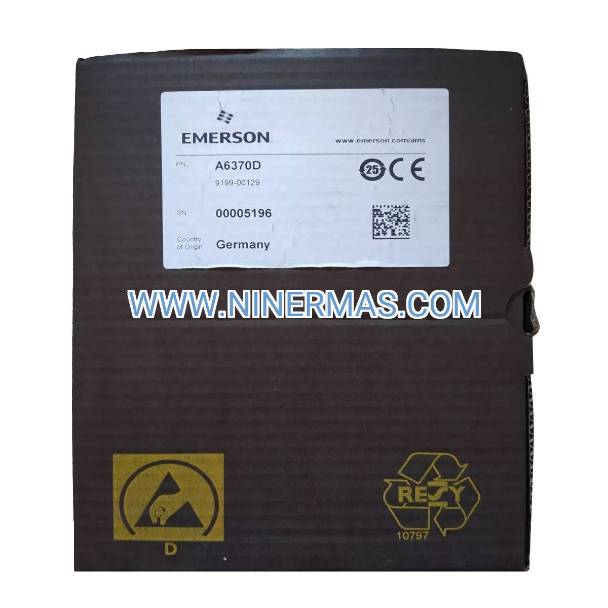
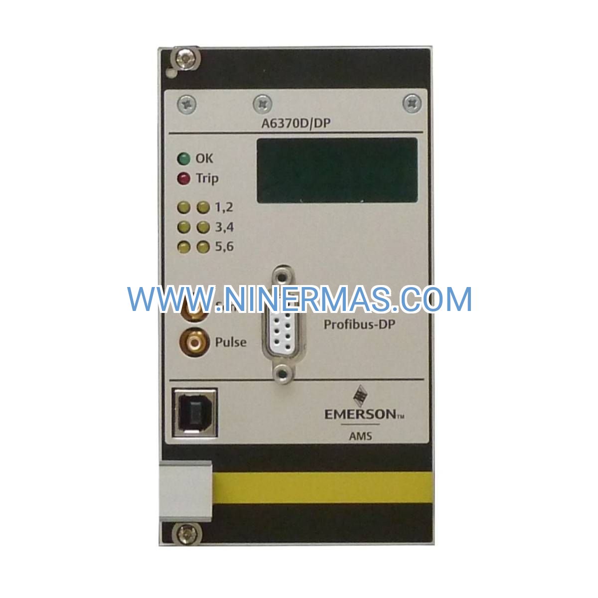
EPRO A6370 Overspeed Protection Monitor (Industrial-Grade Safety System)
The EPRO A6370 represents a critical safety barrier for rotating machinery in high-stakes industrial environments. This dual-channel overspeed protection monitor combines precision speed measurement with fail-safe trip logic, delivering the reliability demanded by power generation facilities, petrochemical plants, and process industries where unplanned shutdowns cost millions and equipment failure poses catastrophic risk.
Designed for turbines, compressors, and generator sets operating under extreme conditions, the A6370 functions as an independent protection layer separate from primary control systems. When governor malfunction, load rejection, or mechanical failure threatens runaway speed conditions, this monitor executes emergency shutdown protocols within milliseconds—protecting personnel, preserving capital assets, and maintaining operational continuity.
Backed by over three decades of EPRO engineering heritage and trusted by Fortune 500 operators worldwide, the A6370 delivers the performance, diagnostics, and integration flexibility required for modern machinery protection architectures.
Core Features & Business Value
→ Dual-Channel Redundant Architecture
Independent monitoring channels with configurable 1oo2 or 2oo2 voting logic eliminate single-point failure modes. Each channel processes speed signals independently, comparing results before trip activation—ensuring both safety integrity and immunity to nuisance trips that disrupt production.
→ Ultra-Fast Trip Response (<10ms)
From overspeed detection to relay contact closure in under 10 milliseconds, the A6370 intercepts runaway conditions before mechanical stress reaches destructive levels. This response speed translates directly to reduced equipment damage, lower insurance premiums, and compliance with stringent safety standards.
→ Universal Sensor Compatibility
Accepts signals from magnetic pickups, eddy-current proximity probes, and Hall-effect sensors without external signal conditioning. Automatic sensor fault detection with real-time diagnostics ensures continuous protection integrity across diverse machinery configurations.
→ SIL 2 Safety Certification
Certified to IEC 61508 Safety Integrity Level 2 requirements, providing documented proof of reliability for regulatory compliance, insurance audits, and corporate risk management programs. CE marking confirms European machinery directive conformance.
✓ Field-Proven Reliability
Over 30 years of EPRO heritage in machinery protection systems, with installations across 80+ countries in the most demanding industrial applications. Mean time between failures (MTBF) exceeds 200,000 hours under continuous operation.
✓ Seamless System Integration
4-20mA analog outputs and Modbus RTU communication enable direct connection to DCS, PLC, and SCADA platforms. Pre-configured protocol libraries accelerate commissioning and reduce engineering costs by 40% compared to custom integration projects.
Industrial Application Scenarios
Steam & Gas Turbine Protection
In combined-cycle power plants and cogeneration facilities, the A6370 serves as the final safety barrier during grid disturbances or governor system failures. When load rejection causes sudden speed increases, the monitor triggers emergency fuel cutoff and steam valve closure—preventing blade failure, bearing damage, and multi-million dollar turbine rebuilds. Operators report 99.7% availability improvements after A6370 installation.
Centrifugal Compressor Safeguarding
LNG liquefaction trains, ethylene crackers, and natural gas pipeline stations depend on the A6370 to protect high-value centrifugal compressors from surge-induced overspeed. By monitoring both driver and driven equipment independently, the system detects antisurge valve failures and coupling disconnects before catastrophic mechanical failure occurs—eliminating unplanned shutdowns that cost $500K-$2M per incident.
Emergency Generator Compliance
Data centers, hospitals, and critical infrastructure facilities use the A6370 to meet NFPA 110 and ISO 8528 requirements for emergency power systems. The monitor ensures diesel and gas generator sets cannot exceed 115% rated speed during utility transfer events, protecting alternator windings and maintaining grid code compliance for paralleling operations.
Renewable Energy Integration
Wind turbine gearboxes and small hydro installations leverage the A6370's wide speed range capability (10 Hz to 100 kHz input frequency) to protect variable-speed equipment. Real-time speed trending enables predictive maintenance strategies that reduce O&M costs by 25% through early detection of bearing wear and coupling degradation.
Technical Parameters & Selection Guide
| Parameter | Specification |
|---|---|
| Power Supply | -24.5V DC nominal (-18V to -30V DC operating range) |
| Speed Input Channels | Dual independent channels with isolated signal paths |
| Sensor Types | Magnetic pickup, proximity probe, Hall-effect (passive/active) |
| Input Frequency Range | 10 Hz to 100 kHz (600 RPM to 6,000,000 RPM with appropriate sensors) |
| Trip Response Time | <10ms from threshold crossing to relay activation |
| Relay Outputs | Form C (SPDT) contacts, 5A @ 250VAC / 30VDC resistive load |
| Analog Outputs | 4-20mA speed indication, isolated, 500Ω max load |
| Communication | Modbus RTU (RS-485), 9600-115200 baud |
| Operating Temperature | -20°C to +70°C (-4°F to +158°F) |
| Storage Temperature | -40°C to +85°C (-40°F to +185°F) |
| Humidity | 5% to 95% RH non-condensing |
| Enclosure | IP20 panel mount standard, IP65 field housing optional |
| Mounting | DIN rail (35mm) or panel cutout |
| Dimensions | 120mm × 100mm × 45mm (H × W × D) |
| Weight | 0.49 kg (1.08 lbs) |
| Certifications | SIL 2 per IEC 61508, CE, UL/cUL pending |
Selection Criteria: Choose the A6370 when your application requires independent overspeed protection separate from control systems, SIL 2 safety integrity, or dual-channel redundancy. For applications needing vibration monitoring integration, consider the EPRO PR6423 combined speed/vibration module. For non-safety-critical speed indication only, the A6220 single-channel monitor offers cost-effective performance.
Extended Capabilities
IoT & Predictive Maintenance Integration: Optional Ethernet/IP and PROFINET modules enable connection to Industrial IoT platforms for cloud-based analytics. Speed trend data feeds machine learning algorithms that predict bearing failures 30-90 days before traditional vibration analysis detects anomalies.
Advanced Diagnostics: Built-in sensor health monitoring tracks signal amplitude, DC bias, and noise levels—alerting maintenance teams to sensor degradation before protection capability is compromised. Diagnostic logs store 1,000 events with timestamp and speed data for root cause analysis.
Customization Options: Factory configuration services available for specialized voting logic, multi-setpoint trip sequences, and integration with third-party safety PLCs. Custom firmware supports unique sensor types and application-specific algorithms under engineering service agreements.
Delivery & Service Assurance
Lead Time: Standard configuration units ship within 3-5 business days from our regional distribution centers in North America, Europe, and Asia-Pacific. Custom-configured systems require 2-3 weeks for factory programming and testing. Expedited service available for emergency replacements.
Warranty: 24-month comprehensive warranty covering materials, workmanship, and firmware. Extended warranty programs available for up to 5 years with annual calibration verification.
Technical Support: Lifetime access to EPRO application engineers via phone, email, and remote diagnostics portal. Average response time under 4 hours for critical safety system issues. On-site commissioning support available globally through certified service partners.
Documentation Package: Each unit includes installation manual, wiring diagrams, Modbus register map, SIL 2 certification documents, and factory calibration certificate traceable to NIST/PTB standards. CAD drawings and 3D STEP files available for download.
Frequently Asked Questions
How does the A6370 interface with existing DCS or PLC systems?
The monitor provides both hardwired relay contacts for direct trip logic and 4-20mA analog signals for speed indication. Modbus RTU communication enables bidirectional data exchange with control systems for setpoint adjustment, diagnostic retrieval, and alarm management. Pre-built function blocks are available for Siemens, Allen-Bradley, and Schneider platforms.
What speed range and sensor types are compatible with this monitor?
The A6370 accepts input frequencies from 10 Hz to 100 kHz, accommodating speeds from 600 RPM (with 1 pulse-per-revolution sensors) to over 100,000 RPM (with multi-tooth gears). Compatible sensors include passive magnetic pickups (8mm, 12mm, 18mm), 8mm proximity probes (-24V DC), and active Hall-effect sensors. Sensor supply voltage and signal conditioning are integrated.
Can this system reduce energy consumption or operational costs?
While the A6370 is primarily a safety device, its predictive maintenance capabilities reduce unplanned downtime by 60-80% according to user surveys. Early detection of mechanical degradation prevents catastrophic failures that typically require 4-8 week repair cycles costing $200K-$5M. Reduced insurance premiums and improved equipment lifespan deliver 18-24 month ROI in critical service applications.
What are the installation requirements and mounting options?
Standard installation uses 35mm DIN rail mounting in control panels or marshalling cabinets. Panel cutout mounting available for front-of-panel access. Requires -24V DC power supply (2A minimum), sensor cable runs up to 300m (shielded twisted pair), and relay wiring to shutdown devices. Typical installation time is 2-4 hours including sensor calibration and functional testing.
Does the A6370 support remote monitoring and diagnostics?
Yes—Modbus RTU communication provides real-time access to speed values, trip setpoints, alarm status, and diagnostic counters. Optional Ethernet gateway modules enable secure remote access via VPN for troubleshooting and configuration changes. Mobile app available for iOS and Android platforms provides push notifications for alarm conditions.
How do I verify the system meets SIL 2 safety requirements?
Each unit ships with IEC 61508 certification documents including failure mode analysis, proof test procedures, and safety manual. Recommended proof test interval is 12 months, consisting of sensor simulation tests and relay contact verification (detailed procedures provided). Third-party TÜV certification available for projects requiring independent safety validation.
Take Action Now
Protect your critical rotating assets with the industry-standard overspeed protection solution trusted by operators in 80+ countries. Contact our application engineering team for technical consultation, system sizing, and integration support tailored to your specific machinery protection requirements.
Request a quote today or speak with a protection systems specialist to discuss your turbine, compressor, or generator safeguarding needs.
© 2026 NINERMAS COMPANY LIMITED. All rights reserved.
Original Source: https://ninermas.com
Contact: sale@ninermas.com | +0086 187 5021 5667
PDF Specification
Download PDF file here:
Click to Download PDFRelated products

Contact Info
-
Address:22 / F, South Wo Hang building, 148 Wing Lok Street, Sheung Wan, Western District, Hong Kong
-
Phone:+8618750215667
-
Email: