ABB RB520 3BSE003528R1 | 16-Channel Relay Output Module for Industrial DCS & Automation Systems
Description
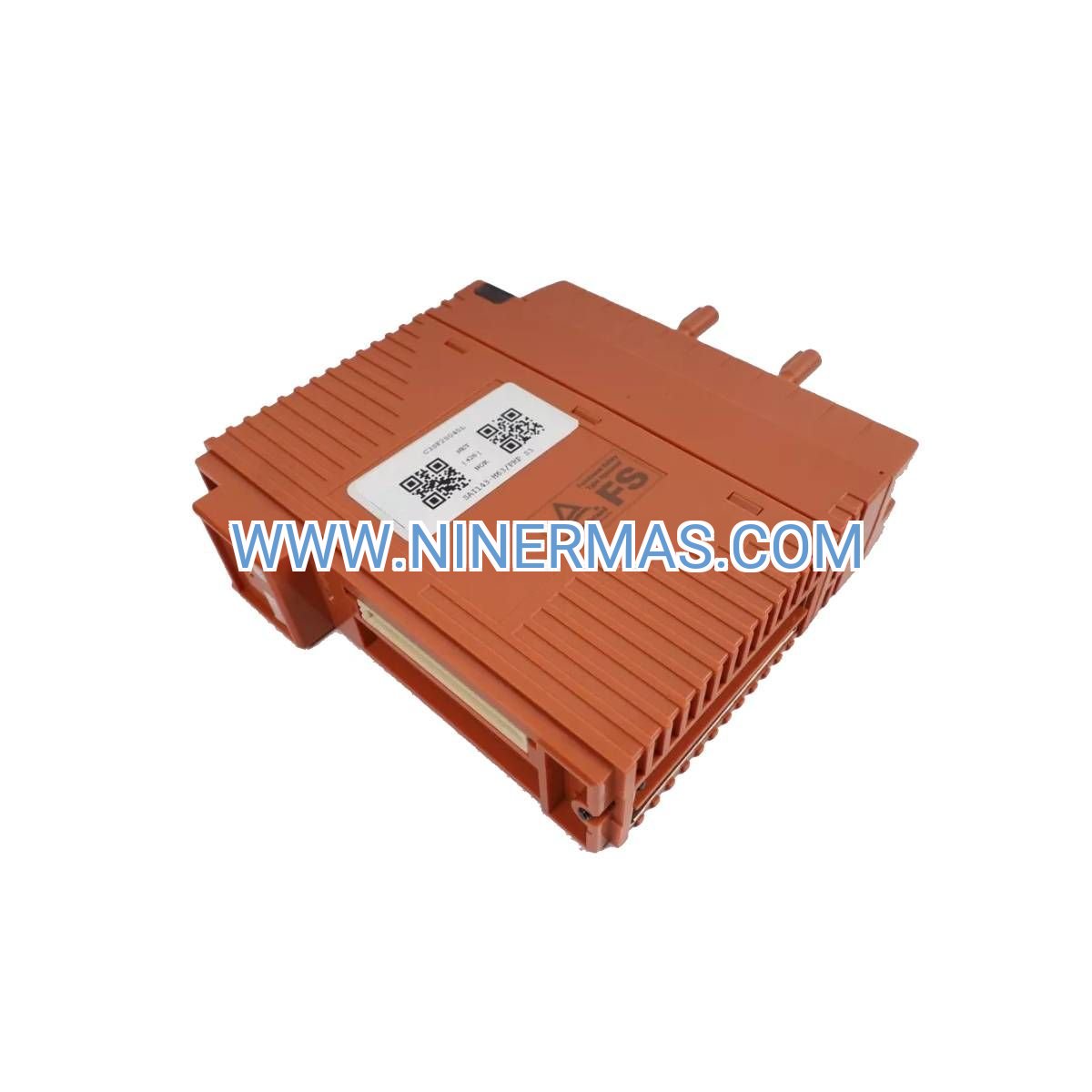
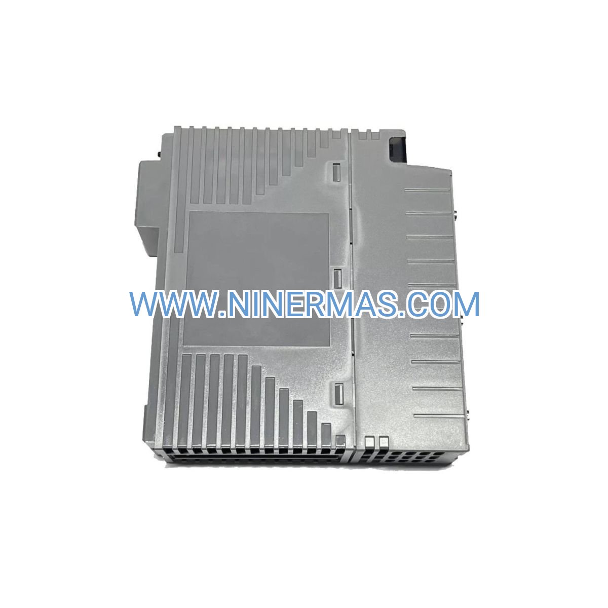
ABB RB520 3BSE003528R1 Relay Output Module (Industrial-Grade 16-Channel Switching Control)
The ABB RB520 3BSE003528R1 is a professional relay output module designed for industrial distributed control systems (DCS), delivering 16 independent relay channels for reliable switching control. Integrated with ABB's Advant OCS and System 800xA platforms, this module enables precise on/off control of field devices through galvanic isolation technology, ensuring stable operation in demanding industrial environments such as process automation, energy management, and discrete manufacturing.
Ideal for applications requiring high-reliability switching—including valve control, motor starters, alarm systems, and interlock circuits—the RB520 addresses common challenges like electrical noise interference, contact bounce, and insufficient isolation between control and field circuits. Its robust design minimizes downtime risks while simplifying maintenance procedures.
With standardized S800 I/O architecture and flexible configuration options, the ABB RB520 suits design engineers, system integrators, OEM manufacturers, and plant maintenance teams. Contact our automation specialists for application-specific selection guidance, technical documentation, and competitive quotations.
Core Features & Advantages
- 16 Independent Relay Channels
Each channel provides SPDT (Form C) contact configuration with galvanic isolation, supporting simultaneous control of multiple field devices while preventing cross-interference between circuits. - High Switching Capacity
Rated for 250VAC/5A or 30VDC/5A per contact, capable of directly driving solenoid valves, contactors, indicator lights, and small motors, reducing the need for intermediate relays. - Robust Electrical Isolation
Provides 2.5kV isolation between control logic and field circuits, protecting sensitive DCS components from voltage spikes, ground loops, and electromagnetic interference (EMI) in harsh industrial settings. - Hot-Swappable Design
Supports online replacement without system shutdown, minimizing production interruptions. Module status LEDs enable rapid fault diagnosis, reducing mean time to repair (MTTR). - Seamless System Integration
Fully compatible with ABB Advant Controller 800 series and System 800xA engineering tools, supporting standard IEC 61131-3 programming languages and pre-configured function blocks for accelerated commissioning. - Comprehensive Protection Mechanisms
Built-in arc suppression circuits, overload protection, and short-circuit safeguards extend relay lifespan (rated for 100,000+ mechanical operations) while ensuring personnel and equipment safety.
Typical Application Scenarios
The ABB RB520 relay output module excels in environments demanding high switching reliability and electrical isolation, particularly in:
- Process Automation & Chemical Plants
Controls on/off valves, pump starters, and emergency shutdown (ESD) systems in oil & gas, petrochemical, and pharmaceutical production lines, ensuring compliance with SIL-rated safety requirements. - Power Generation & Energy Management
Manages circuit breaker trip coils, generator excitation systems, and auxiliary equipment in thermal, hydro, and renewable energy facilities, supporting grid stability and load management. - Water & Wastewater Treatment
Operates dosing pumps, blower motors, and gate valves in municipal water treatment plants, coordinating with SCADA systems for automated process sequencing. - Manufacturing & Discrete Automation
Drives conveyor systems, robotic actuators, and material handling equipment in automotive, electronics, and food & beverage production, integrating with MES/ERP platforms. - Building Automation & HVAC Systems
Controls dampers, fan coil units, and chiller systems in commercial buildings and data centers, optimizing energy efficiency through BMS integration.
Technical Specifications & Selection Guide
To facilitate engineering design and procurement, key specifications are outlined below. Custom configurations are available for project-specific requirements.
| Parameter | Specification |
|---|---|
| Model Number | ABB RB520 3BSE003528R1 |
| Number of Channels | 16 relay outputs (SPDT) |
| Contact Rating | 250VAC/5A resistive, 30VDC/5A resistive |
| Isolation Voltage | 2.5kV (control to field) |
| Operating Voltage | 24VDC nominal (via S800 I/O bus) |
| Response Time | ≤10ms (energize/de-energize) |
| Mechanical Life | 10⁷ operations (no load) |
| Electrical Life | 10⁵ operations (rated load) |
| Operating Temperature | -40°C to +70°C |
| Protection Rating | IP20 (when mounted in enclosure) |
| Dimensions (H×W×D) | 119mm × 70mm × 120mm |
| Mounting | DIN rail (35mm standard) |
| Certifications | CE, UL, ATEX (Zone 2), IECEx |
Selection Recommendations:
When specifying the RB520 module, consider: (1) total number of discrete outputs required, (2) field device voltage/current ratings, (3) environmental conditions (temperature, humidity, vibration), (4) safety integrity level (SIL) requirements, and (5) existing ABB DCS infrastructure. For applications exceeding 250VAC or 5A, external power relays or contactors are recommended. Our engineering team can provide load calculation worksheets and wiring diagrams upon request.
Extended Capabilities
- Redundancy Support: Compatible with ABB's redundant controller configurations (AC 800M High Integrity) for critical process control applications requiring 99.99%+ availability.
- Diagnostic Features: Real-time channel status monitoring via System 800xA, with configurable alarms for contact wear, coil failure, and wiring faults.
- Fieldbus Integration: Operates within S800 I/O clusters supporting PROFIBUS DP, Modbus RTU, and Foundation Fieldbus protocols for multi-vendor system interoperability.
- Harsh Environment Options: Conformal coating available for corrosive atmospheres; extended temperature variants (-55°C to +85°C) for outdoor installations.
Delivery, Service & Quality Assurance
Lead Time: Standard stock items ship within 3-5 business days; custom-configured modules require 10-15 business days. Expedited delivery available for urgent projects.
Warranty: 18-month manufacturer warranty covering material defects and workmanship. Extended service contracts available for critical infrastructure applications.
Technical Support: Complimentary pre-sales engineering consultation, including I/O point allocation, power budget calculations, and cabinet layout reviews. Post-sales support includes remote commissioning assistance and on-site troubleshooting (region-dependent).
Documentation Package: Each module ships with installation manual, terminal wiring diagrams, CAD drawings (DWG/PDF), and System 800xA library files for seamless integration.
Certifications: Factory-tested per IEC 61131-2 standards; compliant with ATEX/IECEx directives for hazardous area installations (Zone 2/Division 2).
Frequently Asked Questions (FAQ)
Q: How does the ABB RB520 relay output module integrate with existing S800 I/O systems?
A: The RB520 mounts directly onto standard S800 I/O clusters via ModuleBus communication. Simply insert the module into an available slot, configure channel parameters in System 800xA Control Builder, and download the configuration—no additional gateways or converters required. Verify power budget capacity of your cluster power supply before installation.
Q: What is the maximum number of RB520 modules supported per I/O cluster?
A: Each S800 I/O cluster (with TB807/TB820 ModuleBus interface) supports up to 12 I/O modules. The actual number depends on total current draw; the RB520 consumes approximately 150mA from the 24VDC bus. Consult the S800 I/O Hardware Manual (3BSE008510) for detailed power calculations.
Q: Can the RB520 switch inductive loads like solenoid valves and motor contactors?
A: Yes, but inductive load ratings are derated to approximately 50% of resistive ratings (e.g., 125VAC/2.5A for AC solenoids). Install external RC snubbers or varistors across inductive loads to suppress voltage transients and extend relay contact life. Refer to application note 3BSE040935 for suppression circuit recommendations.
Q: What environmental protection does the RB520 offer for installation in dusty or humid areas?
A: The module itself is rated IP20 and must be installed within a suitable enclosure (minimum IP54 recommended for industrial environments). For corrosive atmospheres or high-humidity locations, specify conformal-coated versions (suffix "-CC") and ensure adequate ventilation to prevent condensation.
Q: Does the RB520 support remote monitoring and predictive maintenance?
A: Yes, when integrated with System 800xA, each relay channel's operational status, switching cycle count, and fault conditions are logged in the asset management database. Configure trend displays and email/SMS alarms for proactive maintenance scheduling based on contact wear thresholds.
Q: Is the RB520 suitable for safety-instrumented systems (SIS) applications?
A: The standard RB520 is designed for basic process control (BPCS) applications. For SIL 2/3 safety functions, use ABB's dedicated safety I/O modules (e.g., SD820 series) certified per IEC 61508. However, the RB520 can serve as a non-safety output in hybrid architectures where safety logic resides in certified controllers.
Request a Quotation or Technical Consultation
To receive a detailed selection proposal, pricing, or application-specific engineering support, please provide the following information: project name, application description (process type, controlled equipment), total number of relay outputs required, field device voltage/current specifications, environmental conditions (temperature range, hazardous area classification), and existing DCS platform (controller model, I/O cluster configuration). Our automation engineers will respond within 24 hours with tailored recommendations and budget estimates.
© 2026 NINERMAS COMPANY LIMITED. All rights reserved.
Original Source: https://ninermas.com
Contact: sale@ninermas.com | +0086 187 5021 5667
Related products

Contact Info
-
Address:22 / F, South Wo Hang building, 148 Wing Lok Street, Sheung Wan, Western District, Hong Kong
-
Phone:+8618750215667
-
Email: