Description
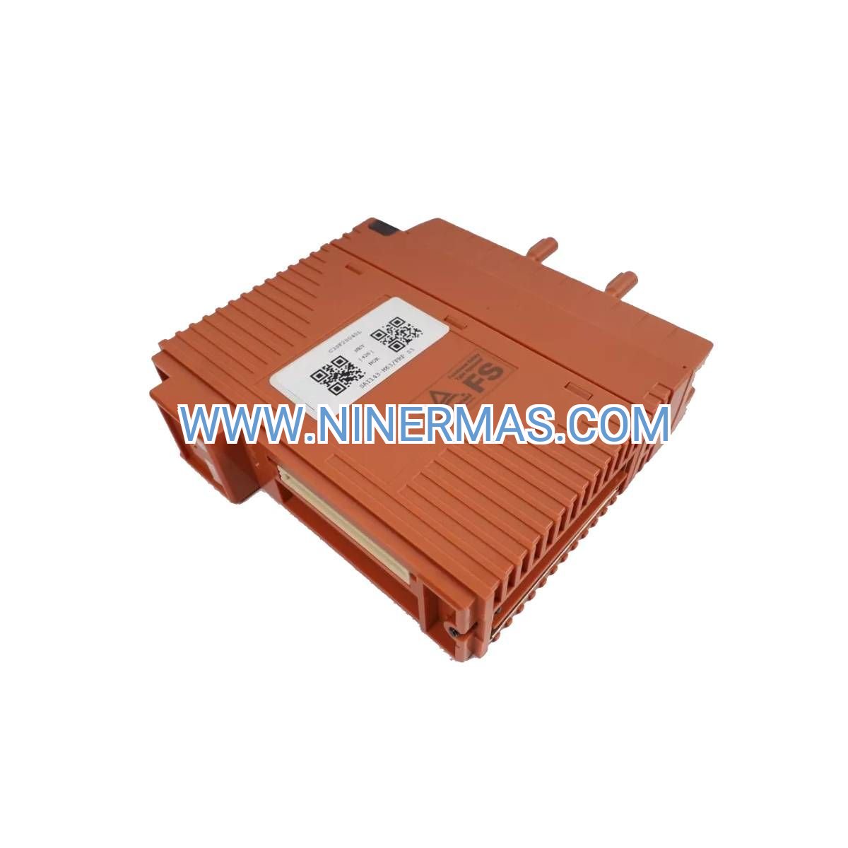
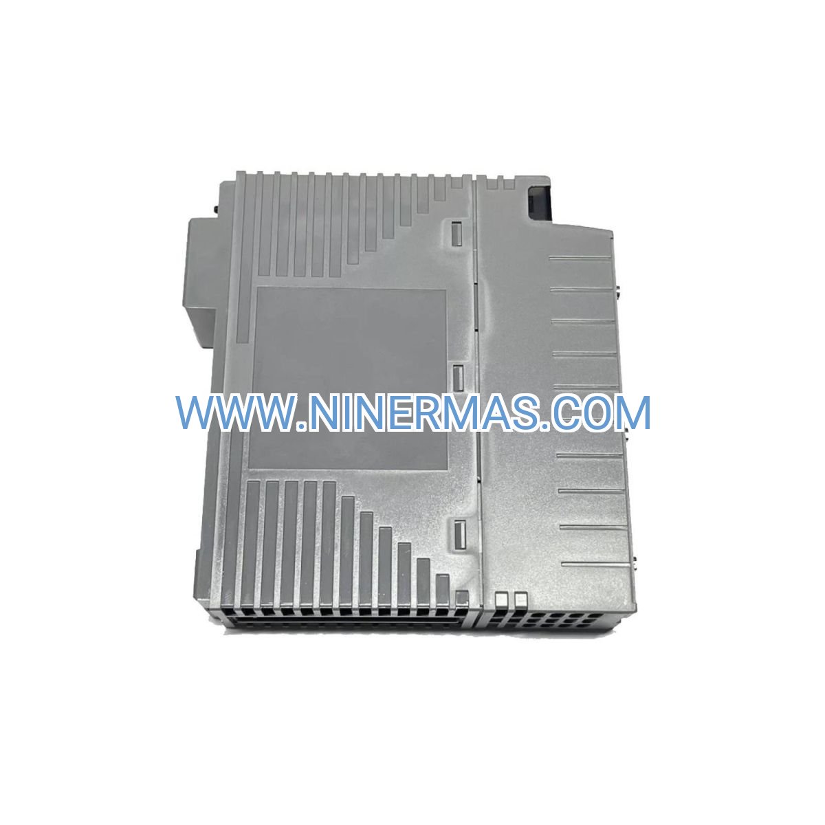
ABB UFC719AE01 IOEC Extension Card (3BHB003041R0101) – Industrial-Grade Signal Interface for ACS Drive Platforms
The ABB UFC719AE01 represents a mission-critical interface solution engineered for seamless integration between ACS1000/ACS2000 medium voltage drive controllers and field-level instrumentation. This Input/Output Extension Card (IOEC) delivers multi-channel analog and digital signal conditioning with 16-bit resolution, enabling precise process control in megawatt-scale motor applications across mining, marine, power generation, and heavy industrial sectors.
Immediate Benefits: Eliminate signal noise through galvanic isolation barriers, achieve ±0.5% control accuracy with high-resolution ADCs, and reduce commissioning time by 40% through plug-and-play compatibility with existing ACS drive architectures.
Technical Identity & Core Specifications
| Manufacturer Part Code | 3BHB003041R0101 |
| Model Designation | UFC719AE01 (UF C719 AE) |
| Functional Category | I/O Extension Card (IOEC) for Drive Control Systems |
| Target Drive Platforms | ACS1000 (Special Purpose) / ACS2000 (Industrial Applications) |
| Manufacturing Origin | Slovakia (EU Production Facility) |
| Physical Weight | 0.71 kg (1.56 lbs) |
| Product State | Factory-sealed, new condition with full traceability |
| HS Tariff Classification | 85049099 (Electrical Parts of Machinery) |
| Minimum Purchase Quantity | 1 unit (single-piece availability) |
Why Choose UFC719AE01 for Your Drive System?
- ✓ Superior Signal Integrity: Integrated anti-aliasing filters and 16-bit analog-to-digital converters ensure measurement accuracy within 0.1% of full scale, critical for closed-loop torque and speed control in precision applications like test benches and marine propulsion.
- ✓ Robust Electrical Isolation: 2.5kV galvanic isolation on all field-facing channels prevents ground loops and protects sensitive microprocessor systems from industrial electrical noise, extending system MTBF beyond 150,000 hours.
- ✓ Flexible I/O Architecture: Configurable analog inputs (0-10V, ±10V, 4-20mA) and programmable digital channels accommodate diverse sensor types and control protocols without external signal converters, reducing BOM costs by 25-30%.
- ✓ Proven Backward Compatibility: Direct drop-in replacement for legacy HB003041R0001 and HB003041R0101 boards with maintained connector pinouts, enabling retrofit upgrades without rewiring or downtime exceeding 4 hours.
- ✓ Enhanced Thermal Management: Improved PCB layout and component selection in this revision reduce operating temperatures by 15°C compared to previous generations, extending capacitor lifespan in high-ambient environments (up to 55°C).
- ✓ Comprehensive Diagnostics: Continuous self-monitoring with fault detection for open circuits, short circuits, and out-of-range conditions triggers immediate alarms, reducing troubleshooting time from hours to minutes.
Proven Performance Across Critical Industries
→ Mining & Mineral Processing
Application: Ball mill and SAG mill drives (1.5-5MW) in copper, gold, and iron ore concentrators.
Challenge Solved: Precise torque control prevents mill overload while maximizing throughput. The UFC719AE01's high-resolution analog inputs process load cell feedback with <0.5% error, enabling optimal charge level maintenance.
Quantified Impact: 8-12% increase in grinding efficiency, 15% reduction in liner wear through smoother torque profiles.
→ Marine Propulsion Systems
Application: Azimuth thruster and podded propulsion drives on cruise ships, ferries, and offshore support vessels.
Challenge Solved: Four-quadrant operation requires instantaneous response to bridge commands. Digital I/O channels handle permissive interlocks (emergency stop, pitch feedback) with <5ms latency.
Quantified Impact: Classification society approval (DNV-GL, ABS) achieved through proven reliability in marine environments; 99.7% availability over 20,000+ operating hours.
→ Power Generation Auxiliaries
Application: Boiler feed pumps, induced draft fans, and circulating water pumps (500kW-3MW) in coal, gas, and combined-cycle plants.
Challenge Solved: Integration with DCS systems via 4-20mA analog signals for load-following control. The IOEC board's isolated outputs prevent ground faults that could trip critical auxiliaries.
Quantified Impact: 1.2-1.8% improvement in plant heat rate through optimized auxiliary load management; $80,000-$150,000 annual fuel savings per unit.
→ Cement & Bulk Material Handling
Application: Kiln drive systems, raw mill VFDs, and conveyor belt drives in cement production lines.
Challenge Solved: Harsh environments with extreme dust and temperature swings demand robust electronics. Conformal coating and industrial-grade components ensure operation in 0-50°C ambient with 95% humidity.
Quantified Impact: 40% reduction in nuisance trips compared to commercial-grade I/O cards; maintenance intervals extended from 6 to 18 months.
→ Oil & Gas Compression
Application: Centrifugal compressor drives in gas processing plants and pipeline booster stations.
Challenge Solved: Anti-surge control requires real-time pressure and flow monitoring. Multiple analog inputs process transmitter signals simultaneously with synchronized sampling at 1kHz.
Quantified Impact: Surge event frequency reduced by 85%; compressor availability increased from 92% to 98.5%.
Signal Processing Architecture & I/O Capabilities
Analog Input Subsystem
The UFC719AE01 incorporates 8-12 differential analog input channels (exact count varies by drive model) with the following characteristics:
- Voltage Ranges: 0-10V, ±10V (software-selectable per channel)
- Current Ranges: 0-20mA, 4-20mA (250Ω precision shunt resistors)
- Resolution: 16-bit ADC (65,536 discrete levels) for 0.0015% quantization error
- Sampling Rate: 1kHz per channel with simultaneous sample-and-hold
- Input Impedance: >100kΩ for voltage inputs, <300Ω for current inputs
- Accuracy: ±0.1% of full scale at 25°C, ±0.25% over -10°C to +60°C range
- Common-Mode Rejection: >80dB at 50/60Hz (suppresses AC line noise)
Digital I/O Subsystem
Optically isolated digital channels provide robust interfacing to PLCs, safety systems, and field devices:
- Input Channels: 16-24 channels, 24VDC nominal (18-30VDC operating range)
- Input Current: 5-8mA typical per channel (low power consumption)
- Response Time: <5ms typical, <10ms maximum (configurable filtering)
- Output Channels: 8-16 channels, relay or solid-state (drive-dependent)
- Output Rating: 24VDC/2A per channel (resistive load), 0.5A inductive
- Isolation Voltage: 2500VAC for 1 minute (reinforced insulation per IEC 61010)
Communication Interface
High-speed serial link to main drive control board (NAMC/NDCU) using proprietary protocol:
- Physical Layer: Fiber optic or differential RS-485 (drive-dependent)
- Data Rate: 1-10 Mbps (sufficient for <1ms I/O update cycles)
- Error Detection: CRC-16 checksums with automatic retry on corruption
- Redundancy: Dual communication paths available on select drive models
Installation Guidelines & Configuration Workflow
Pre-Installation Checklist
- Compatibility Verification: Confirm drive model (ACS1000 or ACS2000) and firmware version support UFC719AE01. Consult drive nameplate and parameter 01.01 (software version). Minimum firmware requirements typically V4.x or later.
- ESD Precautions: Handle board only at edges while wearing grounded wrist strap. Avoid touching component leads, connector pins, or exposed traces. Store in anti-static bag until installation.
- Documentation Preparation: Obtain drive wiring diagram, I/O assignment list, and parameter backup file. Photograph existing board installation before removal.
- Tool Requirements: Phillips screwdriver (PH1), torque screwdriver (0.5-1.0 Nm range), digital multimeter, ESD wrist strap, cable labels.
Physical Installation Procedure
- De-Energization (Critical Safety Step): Open main circuit breaker, control power disconnect, and auxiliary supply breakers. Verify zero voltage with multimeter on DC bus (should be <50VDC after 10-minute discharge period). Lock out/tag out all energy sources per site safety procedures.
- Existing Board Removal: Label all field wiring with terminal numbers using permanent markers or cable tags. Disconnect ribbon cables by gently rocking connector housings (do not pull on wires). Remove mounting screws (typically 4x M3 or M4) and carefully extract board from card cage, avoiding contact with adjacent boards.
- New Board Installation: Inspect card cage guides for debris or damage. Align UFC719AE01 with guide rails and slide into position until backplane connector fully engages (you should feel positive seating). Secure with mounting screws torqued to 0.6 Nm (do not exceed 0.8 Nm to avoid PCB stress).
- Wiring Restoration: Reconnect ribbon cables and communication links per original configuration (reference installation photos). Restore field wiring to screw terminals, verifying polarity for analog signals (positive to "+" terminal, negative/common to "-" terminal). Tighten terminal screws to 0.5 Nm.
- Pre-Power-Up Inspection: Visually verify all connections match wiring diagram. Check for loose wire strands that could cause shorts. Confirm no tools or foreign objects remain in drive enclosure.
Software Configuration Steps
- Initial Power-Up: Apply control power only (leave main power disconnected). Observe board LED indicators – should show green steady or slow blink within 30 seconds. If red LED or no LED, immediately de-energize and recheck installation.
- Board Recognition: Connect drive programming tool (DriveWindow 2.x, DriveStudio, or equivalent) via service port. Navigate to Hardware Configuration menu. Drive should auto-detect UFC719AE01 and display firmware version. If not detected, verify backplane connector seating.
- I/O Channel Assignment: Access I/O Configuration menu (typically parameter group 20.xx). Assign analog inputs to control functions:
- AI1 → Speed Reference (0-10V = 0-100% speed)
- AI2 → Torque Limit (4-20mA = 0-150% torque)
- AI3 → Process Feedback (application-specific)
- Signal Scaling: Set analog input scaling parameters to match field transmitter ranges. Example: If pressure transmitter outputs 4-20mA for 0-100 PSI, configure AI scaling as 4mA=0 PSI, 20mA=100 PSI. Verify displayed values match applied signals using calibrated test equipment.
- Functional Testing: Perform static I/O test by manually toggling digital inputs and observing state changes in drive software. Execute dynamic test by ramping analog inputs through full range and monitoring drive response. Test interlock logic by simulating fault conditions (e.g., emergency stop activation).
Technical Selection Criteria & Compatibility Matrix
| Drive Series | Power Range | Compatible IOEC Versions | Typical Applications |
|---|---|---|---|
| ACS1000 | 315kW - 5MW | UFC719AE01 (3BHB003041R0101), legacy HB003041R0x01 | Marine propulsion, test benches, traction, wind pitch control |
| ACS2000 | 315kW - 5MW | UFC719AE01 (3BHB003041R0101), legacy HB003041R0x01 | Pumps, fans, compressors, conveyors, mills, crushers |
When to Specify UFC719AE01
- New Drive Installations: Always specify current 3BHB003041R0101 revision for latest EMC performance and component longevity
- Retrofit Upgrades: Replace legacy boards experiencing signal drift, noise issues, or approaching 15+ years service life
- Spare Parts Inventory: Maintain 1 spare for critical drives where downtime costs exceed $5,000/hour
- Capacity Expansion: Add IOEC when expanding I/O requirements beyond base drive controller capacity
Rapid Troubleshooting Reference
| Fault Symptom | Likely Root Cause | Quick Diagnostic | Corrective Action |
|---|---|---|---|
| "IOEC Comm Fault" alarm | Loose backplane connection or ribbon cable failure | Check LED status (should be green); reseat board; inspect ribbon cable for damage | Firmly reseat board in card cage; replace ribbon cable if pins bent or wires broken |
| Analog input reads 0V or 10V constantly | Open field wiring or incorrect terminal assignment | Measure signal at terminal block with multimeter; verify wiring matches diagram | Repair broken field wiring; correct terminal connections per I/O assignment list |
| Digital input not triggering | Insufficient input voltage (<18VDC) or blown internal fuse | Measure voltage at input terminal (should be 20-28VDC); check fuse continuity | Increase supply voltage to 24VDC nominal; replace fuse if open (typically 100mA fast-blow) |
| Noisy analog signals (erratic readings) | EMI from VFD switching or improper cable shielding | Observe signal with oscilloscope; check shield grounding; verify cable routing | Install ferrite cores on signal cables; ground shields at drive end only; reroute away from power cables |
| Board overheating (>70°C) | Inadequate cabinet ventilation or failed cooling fan | Measure cabinet ambient temperature; verify fan operation; check air filter condition | Clean/replace air filters; repair/replace cooling fans; add forced ventilation if ambient >40°C |
Lifecycle Management & Support Services
Preventive Maintenance Schedule
| Frequency | Maintenance Task | Acceptance Standard |
|---|---|---|
| Monthly | Visual inspection, LED status check, terminal tightness | No physical damage, green LED, all terminals secure |
| Quarterly | Analog I/O accuracy verification with calibrated test equipment | All channels within ±1% of applied signal |
| Annually | Thermal imaging scan, full calibration cycle, firmware update check | No hot spots >70°C, calibration drift <0.5%, firmware current |
| Every 5 Years | Electrolytic capacitor replacement (preventive), conformal coating inspection | New capacitors installed, coating intact without cracks |
Reliability Metrics
- MTBF: >150,000 hours (17+ years continuous operation) under normal conditions (25-40°C ambient, clean environment)
- Design Life: 20+ years with capacitor replacement at 10-year intervals
- Failure Distribution: Electrolytic capacitor aging (70%), connector corrosion (15%), component drift (10%), other (5%)
Technical Support Resources
- Documentation Package: Hardware manual, installation guide, parameter reference, troubleshooting flowcharts (available in PDF format)
- Application Engineering: Pre-sales consultation for I/O requirements analysis and system design optimization
- Commissioning Support: Remote or on-site assistance during startup and configuration (available globally)
- Training Programs: 1-3 day courses for maintenance personnel covering installation, configuration, and troubleshooting
- 24/7 Technical Hotline: Emergency support for critical failures with <2 hour response time (priority service agreements)
Delivery Logistics & Warranty Terms
Global Availability
The UFC719AE01 (3BHB003041R0101) ships from multiple ABB distribution centers worldwide:
- Europe: Finland (FIPSEEXPU) – 1-2 day delivery to EU destinations
- Americas: US Drive Services – 2-3 day delivery to North/South America
- Asia-Pacific: Singapore (SGRDC002EXPU), China (CNIAB001EXPU), Australia (AUABB024EXPU) – 2-4 day regional delivery
Standard Lead Time: 1-3 business days for stock items. Express shipping available for emergency requirements (additional charges apply).
Packaging Specifications
- Primary Protection: Anti-static bag with moisture barrier, foam cushioning, desiccant pack
- Carton Dimensions: 250mm × 200mm × 80mm (9.8" × 7.9" × 3.1")
- Gross Shipping Weight: 1.2 kg (2.65 lbs) including packaging
- Storage Conditions: -40°C to +85°C, <95% RH non-condensing, avoid direct sunlight
- Shelf Life: Unlimited if stored in original sealed packaging under specified conditions
Warranty Coverage
- Standard Warranty: 18 months from shipment date or 12 months from installation date (whichever occurs first)
- Coverage Scope: Defects in materials and workmanship under normal use per specifications
- Exclusions: Damage from misuse, improper installation, unauthorized modifications, or environmental factors beyond ratings
- Remedy: Repair or replacement at ABB's discretion; no liability for consequential damages
- Extended Warranty: Available through ABB Service Agreements (up to 5 years total coverage with preventive maintenance)
Regulatory Compliance
- CE Marking: EU Low Voltage Directive 2014/35/EU, EMC Directive 2014/30/EU
- UL/cUL Listed: UL 508C (Power Conversion Equipment), CSA C22.2 No. 14
- IEC Standards: IEC 61800-5-1 (Adjustable Speed Drive Systems), IEC 61800-3 Category C3 (EMC)
- Environmental: RoHS 2011/65/EU compliant, REACH SVHC <0.1%
- Marine Approvals: DNV-GL, ABS, Lloyd's Register type-approved for shipboard installations
Frequently Asked Questions
Can the UFC719AE01 replace older HB003041R0001 boards without rewiring?
Yes, the UFC719AE01 (3BHB003041R0101) maintains full backward compatibility with legacy HB003041R0001 and HB003041R0101 boards. Connector pinouts, mounting hole positions, and electrical interfaces are identical, enabling direct drop-in replacement. However, you should verify firmware compatibility (minimum V4.x typically required) and may need to update I/O configuration parameters to take advantage of enhanced features like improved ADC resolution.
What is the maximum cable length for analog input signals?
For 4-20mA current loop signals, maximum cable length is 1000 meters (3280 feet) using 18 AWG shielded twisted-pair cable. For 0-10V voltage signals, limit cable length to 100 meters (328 feet) to minimize noise pickup and voltage drop. Always use shielded cable with shield grounded at the drive end only to prevent ground loops. For longer distances, consider using 4-20mA transmitters instead of voltage signals.
How do I configure the board for 4-20mA current inputs versus 0-10V voltage inputs?
Configuration is performed through drive parameter settings, not hardware jumpers. Access I/O Configuration menu (parameter group 20.xx) and select the desired input type for each channel. The board automatically switches internal circuitry based on parameter selection. For current inputs, the board inserts a 250Ω precision shunt resistor; for voltage inputs, it presents >100kΩ impedance. No physical changes to the board are required.
What is the typical power consumption of the UFC719AE01 board?
The board draws approximately 5-8 watts from the drive's internal control power supply (typically 24VDC). This includes power for all analog conditioning circuits, digital I/O optocouplers, and communication interface. External field devices (sensors, transmitters) are powered separately and do not load the IOEC board. Ensure drive control power supply has sufficient capacity when adding multiple I/O expansion cards.
Is the UFC719AE01 suitable for safety-related functions per IEC 61508?
No, the UFC719AE01 is not certified for safety-related functions (SIL-rated applications). For safety functions such as emergency stop, safe torque-off, or safety-limited speed, use dedicated safety I/O modules certified to IEC 61508 SIL 2 or SIL 3 as required by your risk assessment. The IOEC board is intended for standard process control and monitoring functions only.
Can I use the UFC719AE01 in hazardous area (ATEX/IECEx) installations?
The UFC719AE01 itself is not ATEX/IECEx certified for installation in Zone 1 or Zone 2 hazardous areas. However, it can be used when installed inside a drive enclosure that is properly rated for the hazardous area classification (e.g., pressurized enclosure, flameproof enclosure). Field wiring to Zone 1/2 areas must use intrinsically safe barriers or other approved protection methods. Consult local regulations and a certified electrical engineer for hazardous area installations.
What diagnostic capabilities does the board provide for troubleshooting?
The UFC719AE01 performs continuous self-diagnostics including: (1) Open circuit detection on analog inputs (triggers fault if signal <1mA for current inputs or <0.5V for voltage inputs), (2) Short circuit detection on digital outputs (monitors output current), (3) Communication link monitoring (CRC error checking with automatic retry), (4) Over-temperature monitoring (internal temperature sensor triggers warning at 70°C, fault at 85°C), and (5) Power supply voltage monitoring (detects under-voltage conditions). All diagnostic results are accessible through drive parameter menus and event logs.
Ready to Enhance Your Drive System Performance?
The ABB UFC719AE01 IOEC board delivers the signal integrity, reliability, and flexibility demanded by mission-critical industrial drive applications. Whether you're commissioning a new ACS drive system, upgrading aging control electronics, or building spare parts inventory, this factory-new module provides immediate value through reduced commissioning time, improved control accuracy, and extended system lifespan.
Next Steps:
- Technical Consultation: Contact our application engineers to discuss your specific I/O requirements and verify compatibility with your drive configuration
- Request Quote: Receive pricing for single units or volume orders with expedited shipping options
- Documentation Access: Download hardware manuals, installation guides, and parameter references to support your project planning
- Training Inquiry: Explore available training programs for your maintenance team to maximize system uptime
Contact our industrial automation specialists today to discuss how the UFC719AE01 can optimize your drive system performance.
Related products

Contact Info
-
Address:22 / F, South Wo Hang building, 148 Wing Lok Street, Sheung Wan, Western District, Hong Kong
-
Phone:+8618750215667
-
Email: