Original Industrial Spare Part
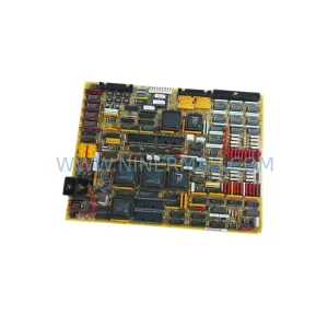
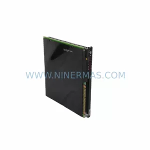
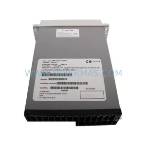
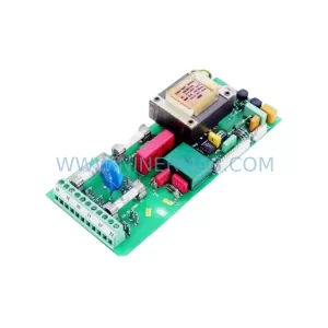
Alstom DFI-100-340F Retrofit-Compatible Flame Indicator
Verify the part, confirm the platform family, and move straight into quotation with the right commercial details.
RFQ Ready
- SKUDFI-100-340F
- CategoryPLC & Industrial Automation Modules
- BrandALSTOM
- SupportAvailability, lead time, condition, and shipping coordination
How Buyers Usually Use This Page
- Confirm the exact part number and platform family before sending the quote request.
- Use direct email when quantity, condition, and destination are already defined internally.
- Switch to the broader brand or category archive when you need alternates nearby.
Series Navigation
Move through the most common platform families behind this part.
Product RFQ
Send this part directly for quotation.
Include quantity, required condition, destination country, and target delivery timing. Current reference: Alstom DFI-100-340F Retrofit-Compatible Flame Indicator with SKU DFI-100-340F.
Alstom DFI-100-340F Retrofit-Compatible Flame Indicator: Legacy System Compatibility & Smooth Upgrade Path
The Alstom DFI-100-340F is a diagnostic flame indicator module designed for industrial combustion monitoring and burner management systems. As legacy control platforms age and original spare parts reach end-of-life, the DFI-100-340F has become a critical retrofit component for power generation facilities, process plants, and industrial boiler systems that rely on Alstom’s DFI series flame detection architecture. NINERMAS maintains verified stock of the DFI-100-340F to support planned maintenance shutdowns, emergency replacements, and phased control system modernization projects.
Whether you are replacing a failed unit on an aging burner management panel, upgrading a discontinued flame scanner interface, or migrating from an obsolete DFI-series rack to a current-generation safety control platform, the DFI-100-340F provides a reliable, tested, and immediately deployable solution. Each unit shipped by NINERMAS undergoes pre-shipment functional verification and is covered by a 12-month warranty from the date of delivery.
Upgrade Compatibility Table
| Parameter | DFI-100-340F Specification | Retrofit Notes |
|---|---|---|
| Module Type | Diagnostic Flame Indicator | Direct replacement for DFI-100 series variants |
| Mounting | DIN rail / panel rack | Confirm backplane slot pitch before installation |
| Power Supply | 24 VDC nominal | Verify PSU capacity; add buffer if replacing multiple modules |
| Signal Interface | Analog + discrete I/O | Check terminal block wiring against original loop drawings |
| Communication | Hardwired / serial link | Confirm protocol compatibility with upstream BMS or DCS |
| Replacement Scope | Drop-in for DFI-100-340F | No firmware re-flash required in most configurations |
| Commissioning | On-site calibration recommended | Flame threshold and scanner gain settings must be verified |
| Warranty | 12 Months | Covered from date of shipment by NINERMAS |
Retrofit Planning for Existing Automation Systems
Successful integration of the DFI-100-340F into an existing burner management or combustion control system requires careful pre-engineering. Before ordering, maintenance engineers should pull the original loop diagrams and confirm the terminal block layout on the existing flame indicator chassis. In many legacy installations, the DFI-100-340F shares a common rack with other Alstom DFI-series modules — such as the DFI-100-320F scanner interface card and the DFI-100-360 amplifier board — and the backplane connector pinout must be verified to ensure mechanical and electrical compatibility.
Power supply capacity is a frequent oversight during retrofit planning. If the existing 24 VDC rail is already loaded by other modules — including relay output cards, analog input modules, or communication gateway units — adding a replacement DFI-100-340F without recalculating the total current draw can cause voltage sag and intermittent faults. It is advisable to audit the full rack power budget and, where necessary, install a supplementary DIN-rail power supply module before proceeding.
Terminal wiring adaptation is another key consideration. Older installations may use screw-type terminal blocks with non-standard wire gauges, while the replacement module may require spring-cage or push-in terminals. In such cases, a terminal adapter plate or re-termination of the field wiring may be necessary. Engineers should also confirm the flame scanner cable routing and shielding continuity, as signal degradation on the scanner input can produce nuisance trips or missed flame detection events after module replacement.
For systems that interface the DFI-100-340F with a distributed control system (DCS) or safety instrumented system (SIS), the communication link between the flame indicator module and the upstream controller — whether via hardwired discrete signals, a serial data link, or a fieldbus segment — must be validated after replacement. In some configurations, the DCS I/O card assignment or the SIS logic solver input channel mapping may need to be updated to reflect the new module’s address or signal range. HMI faceplate graphics tied to the original flame indicator tag should also be reviewed to confirm that alarm setpoints, scanner status displays, and burner permissive interlocks remain correctly mapped.
Where the retrofit involves migrating from an entirely obsolete control platform — for example, replacing a legacy Alstom Alspa or Controbloc-era burner management panel with a modern safety PLC — the DFI-100-340F can serve as an interim flame detection front-end while the broader migration is staged across multiple outages. This approach allows the plant to maintain operational continuity on the existing flame detection infrastructure while progressively decommissioning obsolete I/O racks, replacing aging relay logic panels, and re-engineering the burner sequencing logic in the new control environment.
Downtime Control During System Migration
Minimizing unplanned downtime is the primary concern for any maintenance team undertaking a flame indicator replacement or burner management system upgrade. The DFI-100-340F retrofit process is designed to be completed within a planned maintenance window, typically during a scheduled boiler outage or combustion system inspection. To protect the original control program logic, engineers should export and archive the existing BMS configuration — including flame scanner calibration data, burner sequencing timers, and interlock setpoint tables — before any hardware is disturbed.
Where the plant operates multiple burners on a common flame management rack, a phased replacement strategy is recommended: replace and commission one flame indicator module at a time, verify scanner signal integrity and flame detection response before proceeding to the next channel. This approach limits the scope of any single intervention and allows the control room to maintain partial combustion capacity throughout the migration.
Pre-staging the replacement DFI-100-340F unit on a bench test rig — using a portable flame simulator or UV/IR test source — before bringing it to the field significantly reduces on-site commissioning time. NINERMAS performs a pre-shipment functional test on every DFI-100-340F unit, providing a test report that can be used as the baseline for site acceptance testing. Upon installation, the field commissioning team should verify flame threshold sensitivity, scanner gain alignment, and the response time of the discrete output signals to the BMS logic solver before returning the burner to service.
Retrofit Support FAQ
Q: Is the DFI-100-340F a direct drop-in replacement for other DFI-100 series variants?
A: The DFI-100-340F is designed as a replacement within the Alstom DFI-100 flame indicator family. However, variant suffixes (e.g., -320F, -360, -380) may indicate differences in scanner input type, output relay configuration, or amplifier gain range. Always cross-reference the original module’s nameplate data and loop diagram before ordering to confirm compatibility.
Q: What pre-shipment testing does NINERMAS perform on the DFI-100-340F?
A: Each unit undergoes functional verification including power-up self-test, input signal response check, and discrete output relay actuation test. A test report is included with shipment. All units are covered by a 12-month warranty from the date of delivery.
Q: How do I confirm terminal wiring compatibility before installation?
A: Obtain the original installation drawing for the existing DFI-100-340F and compare the terminal block layout with the replacement unit’s wiring diagram. Pay particular attention to scanner input polarity, power supply terminal assignment, and the discrete output wiring to the BMS relay panel. If drawings are unavailable, NINERMAS technical support can assist with cross-referencing based on the original module’s part number and serial number.
Q: What is the typical lead time and inventory availability?
A: NINERMAS maintains stock of the DFI-100-340F for immediate dispatch. Standard lead time for in-stock units is 3–7 business days for international shipments. For urgent requirements, expedited shipping options are available. Contact our sales team to confirm current inventory status before placing your order.
| Product Series | Other series |
|---|
Catalog Continuation
More ALSTOM modules in the catalog.
Use the brand lane to compare nearby part numbers, platform-adjacent modules, and other inquiry-ready listings before sending your final RFQ.
Catalog Continuation
Alternative parts within PLC & Industrial Automation Modules.
Stay inside the same system family when you need substitutes, adjacent modules, or a broader shortlist for procurement review.