Original Industrial Spare Part
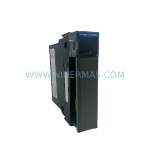
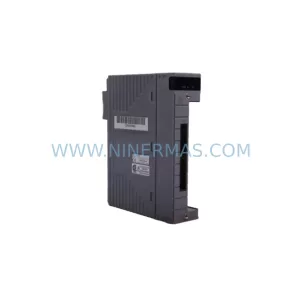
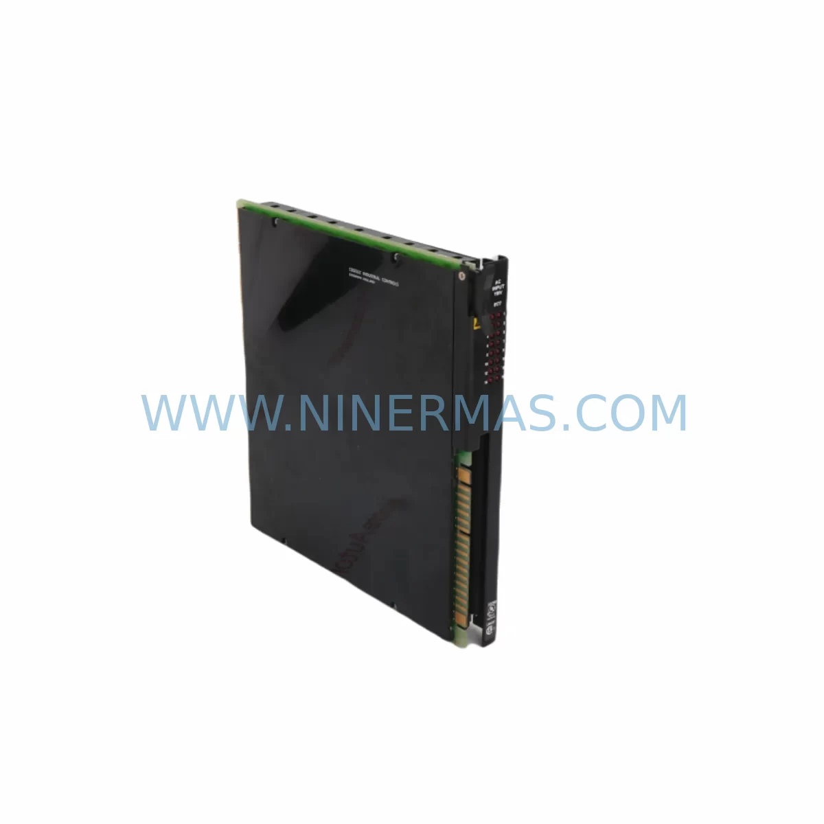
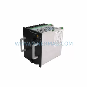
Alstom 8177-4002 Retrofit Input Module for Legacy Systems
Verify the part, confirm the platform family, and move straight into quotation with the right commercial details.
RFQ Ready
- SKU8177-4002
- CategoryDCS Distributed Control Systems
- BrandALSTOM
- SupportAvailability, lead time, condition, and shipping coordination
How Buyers Usually Use This Page
- Confirm the exact part number and platform family before sending the quote request.
- Use direct email when quantity, condition, and destination are already defined internally.
- Switch to the broader brand or category archive when you need alternates nearby.
Series Navigation
Move through the most common platform families behind this part.
Product RFQ
Send this part directly for quotation.
Include quantity, required condition, destination country, and target delivery timing. Current reference: Alstom 8177-4002 Retrofit Input Module for Legacy Systems with SKU 8177-4002.
Alstom 8177-4002 Retrofit Input Module for Legacy Systems
The Alstom 8177-4002 is a ruggedized discrete input module engineered for deployment within the ALSPA 8000 distributed control system (DCS) platform. Designed to withstand the demanding electrical and thermal conditions of heavy industrial environments — including power generation, rail traction control, and process automation — this module provides reliable digital signal acquisition from field devices such as limit switches, proximity sensors, relay contacts, and pushbutton stations. As original ALSPA 8000 hardware reaches end-of-life and spare parts become increasingly scarce, the 8177-4002 has become a critical retrofit component for maintenance teams seeking to extend the operational lifespan of existing control architectures without committing to a full platform migration.
For facilities operating legacy Alstom DCS installations, sourcing a verified replacement 8177-4002 is often the fastest and most cost-effective path to restoring system availability after an unplanned module failure. Unlike a full control system overhaul — which may require months of engineering, commissioning, and operator retraining — a direct module swap preserves the existing program logic, HMI screen layouts, communication topology, and I/O addressing structure. This approach dramatically reduces both downtime exposure and project risk, making the 8177-4002 an essential item in any long-term spare parts strategy for ALSPA-based installations.
Upgrade Compatibility Table
| Parameter | Specification / Retrofit Guidance |
|---|---|
| Module Type | Discrete (Digital) Input Module |
| Platform Compatibility | Alstom ALSPA 8000 DCS — direct slot-compatible replacement |
| Input Channel Count | 16-channel discrete input (24 VDC nominal field voltage) |
| Backplane Interface | ALSPA 8000 standard backplane bus — no adapter required |
| Module Addressing | Hardware DIP switch / backplane slot-based addressing; verify against existing I/O map before installation |
| Terminal Wiring | Screw-terminal field wiring connector; retain original wiring harness for direct reconnection |
| Power Consumption | Confirm rack power budget against installed 8171-4003 power supply module capacity before adding modules |
| Communication Compatibility | Compatible with ALSPA 8000 internal DCS bus; no protocol conversion required for same-platform replacement |
| HMI Integration | Existing HMI tag assignments and screen graphics remain valid after direct module replacement |
| Installation Space | Standard ALSPA 8000 single-slot form factor; verify rack slot availability in existing 8175-4003 backplane/rack assembly |
| Pre-Shipment Testing | Each unit function-tested prior to dispatch; test report available on request |
| Warranty | 12-Month Warranty — covers manufacturing defects and functional failure under normal operating conditions |
Retrofit Planning for Existing Automation Systems
Successful integration of the 8177-4002 into an existing ALSPA 8000 installation requires a structured pre-installation review. Before removing the failed module, maintenance engineers should document the current slot address, field wiring terminal assignments, and the corresponding I/O tag list entries in the DCS configuration database. This baseline record ensures that the replacement module can be addressed identically to its predecessor, avoiding any need to modify the application program or retag field instruments.
Power budget verification is a frequently overlooked step in retrofit planning. The 8171-4003 power supply module serving the affected rack must have sufficient headroom to support the 8177-4002 alongside all other installed modules. If the rack is operating near its rated load, consider redistributing modules across available rack slots or evaluating whether an additional power supply module is warranted before proceeding.
The physical installation environment also demands attention. The 8175-4003 backplane and rack assembly must be inspected for connector pin condition, backplane bus integrity, and slot locking mechanism functionality. Corroded or mechanically damaged backplane connectors are a common root cause of intermittent module faults in aging installations and should be addressed before inserting the replacement 8177-4002.
For sites where the ALSPA 8000 platform interfaces with upstream SCADA systems or plant historians via serial or Ethernet communication links, the 8174-4001 communication module configuration should be reviewed to confirm that the I/O data published by the 8177-4002 channel block is correctly mapped within the communication module’s data table. Similarly, if the installation includes an 8176-4001 CPU controller module, the application program should be verified to confirm that the input channel references associated with the 8177-4002 slot address are active and correctly configured in the scan cycle.
Where field signals originate from long cable runs or noisy industrial environments, the use of an 8178-4002 signal isolator in the field wiring circuit can significantly improve input signal integrity and protect the module’s input circuitry from transient overvoltage events. This is particularly relevant in retrofit scenarios where existing cable infrastructure may not meet current EMC standards.
For sites undertaking a broader I/O expansion alongside the module replacement — for example, adding new field instruments to support a process upgrade — the 8172-4001 discrete output module and 8173-4002 analog input module are commonly deployed in parallel with the 8177-4002 to extend the system’s field interface capability without requiring a controller platform change. The 8181-4001 relay output module is also frequently specified in the same retrofit scope where hardwired interlock outputs are required alongside the new discrete inputs.
HMI continuity is a critical success factor in any retrofit project. Where the installation uses an 8179-4001 HMI interface module or a connected operator workstation running ALSPA graphics, the existing screen objects bound to the 8177-4002 input channels will continue to function correctly after a direct module replacement, provided the slot address and tag assignments are preserved. No HMI reconfiguration is required under these conditions.
Finally, for sites where the application program requires modification — for example, to accommodate a revised I/O assignment or to update interlock logic — the 8180-4002 programming cable provides the physical interface between the engineering workstation and the ALSPA 8000 CPU for program download and online monitoring during commissioning.
Downtime Control During System Migration
Minimizing unplanned downtime is the primary operational objective when replacing a failed 8177-4002 in a live production environment. The most effective strategy is to maintain a pre-tested spare module on-site, configured and addressed to match the installed unit, so that a hot-swap replacement can be completed within a single planned maintenance window rather than requiring an extended outage while a replacement is sourced and shipped.
Where a pre-tested spare is not available and an emergency replacement is required, the following sequence is recommended to protect program logic integrity and minimize field control disruption. First, place the affected control loop in manual mode at the DCS operator station to prevent uncontrolled process responses during the module swap. Second, isolate field power to the affected terminal block before disconnecting the wiring harness. Third, remove the failed 8177-4002 and insert the replacement module into the same backplane slot, ensuring the slot address DIP switches are set identically to the original. Fourth, reconnect the field wiring harness and restore field power. Fifth, verify input channel status at the DCS operator station before returning the loop to automatic control.
For planned retrofit projects involving multiple module replacements across a rack or cabinet, a phased approach — replacing one module per maintenance window — allows the production process to continue operating on the remaining I/O while each replacement is verified in sequence. This approach is particularly effective when combined with a pre-shipment function test report for each 8177-4002 unit, which provides documented evidence of module functionality before installation and reduces the risk of introducing a second fault during the retrofit.
Communication link continuity should also be monitored throughout the replacement process. If the ALSPA 8000 system uses a redundant communication architecture, confirm that the standby communication path remains active during the module swap to prevent a loss of SCADA visibility at the control room level.
Retrofit Support FAQ
Q1: Is the 8177-4002 a direct drop-in replacement for the original Alstom ALSPA 8000 discrete input module?
A: Yes. The 8177-4002 is slot-compatible with the ALSPA 8000 backplane and uses the same terminal wiring connector as the original module. No mechanical adapters or wiring modifications are required for a direct replacement. Module addressing is set via DIP switch to match the original slot configuration.
Q2: What pre-installation checks are required before fitting the replacement module?
A: Verify the rack power budget against the 8171-4003 power supply module capacity, inspect the 8175-4003 backplane connector pins for corrosion or damage, confirm the slot address DIP switch settings match the original module, and review the I/O tag list to ensure the channel assignments are correctly documented before removal of the failed unit.
Q3: Has the replacement 8177-4002 been tested before shipment?
A: Yes. Each unit undergoes a functional test prior to dispatch to verify input channel operation across all 16 channels. A test report is available on request. Units are supplied with a 12-month warranty covering manufacturing defects and functional failure under normal operating conditions.
Q4: What is the typical lead time and stock availability for the 8177-4002?
A: Stock availability is maintained to support emergency replacement requirements. Lead time for in-stock units is typically 3–7 business days for international shipment. For urgent requirements, expedited shipping options are available. Contact our team to confirm current stock status and delivery schedule for your location.
| Product Series | Legacy |
|---|
Catalog Continuation
More ALSTOM modules in the catalog.
Use the brand lane to compare nearby part numbers, platform-adjacent modules, and other inquiry-ready listings before sending your final RFQ.
Catalog Continuation
Alternative parts within DCS Distributed Control Systems.
Stay inside the same system family when you need substitutes, adjacent modules, or a broader shortlist for procurement review.