Original Industrial Spare Part
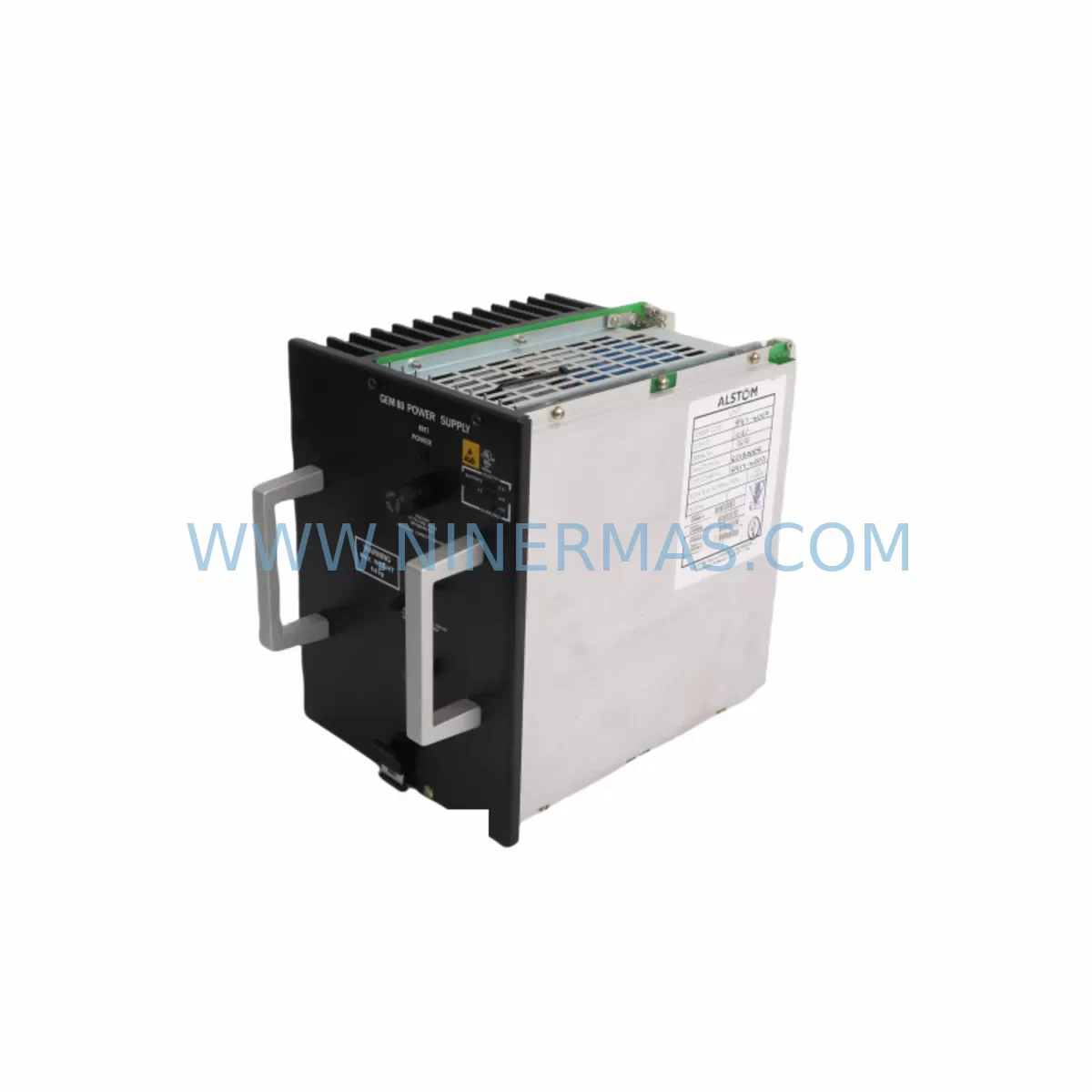
ALSTOM 8917-4003 Retrofit-Compatible Power Module for Legacy Systems
Verify the part, confirm the platform family, and move straight into quotation with the right commercial details.
RFQ Ready
- SKU8917-4003
- CategoryDCS Distributed Control Systems
- BrandALSTOM
- SupportAvailability, lead time, condition, and shipping coordination
How Buyers Usually Use This Page
- Confirm the exact part number and platform family before sending the quote request.
- Use direct email when quantity, condition, and destination are already defined internally.
- Switch to the broader brand or category archive when you need alternates nearby.
Series Navigation
Move through the most common platform families behind this part.
Product RFQ
Send this part directly for quotation.
Include quantity, required condition, destination country, and target delivery timing. Current reference: ALSTOM 8917-4003 Retrofit-Compatible Power Module for Legacy Systems with SKU 8917-4003.
ALSTOM 8917-4003 Retrofit-Compatible Power Module for Legacy Systems
The ALSTOM 8917-4003 is a retrofit-compatible power module engineered to serve as a direct replacement for end-of-life and discontinued power supply units within ALSTOM’s Legacy Power Series control architecture. As industrial facilities face increasing pressure to extend the operational life of aging automation infrastructure, the 8917-4003 provides a reliable, drop-in upgrade path that eliminates the need for full panel redesign or controller replacement. This module is pre-shipment tested, backed by a 12-month warranty, and maintained in ready stock to support urgent maintenance windows and planned retrofit projects alike.
Facilities running legacy ALSTOM distributed control systems (DCS) or programmable logic controller (PLC) platforms frequently encounter power supply failures that threaten production continuity. The 8917-4003 addresses this challenge by maintaining electrical compatibility with original backplane connectors, terminal block layouts, and rack mounting dimensions found in the Legacy Power Series chassis. Engineers can install this module without modifying existing wiring harnesses, reducing retrofit labor hours and minimizing exposure to commissioning errors.
When planning a retrofit around the 8917-4003, site engineers should verify the following parameters against the existing installation: input voltage range and phase configuration, output DC rail voltages and current capacity, backplane connector pinout and keying, DIN rail or rack slot width, and any redundancy relay or status signal wiring connected to the original unit. Confirming these details before ordering ensures a smooth swap-out during the scheduled maintenance window.
Upgrade Compatibility Table
| Parameter | Details |
|---|---|
| SKU / Part Number | 8917-4003 |
| Brand / Series | ALSTOM Legacy Power Series |
| Module Type | Retrofit-Compatible Power Module |
| Backplane Interface | Compatible with Legacy Power Series rack backplane connectors |
| Mounting | Standard rack slot; confirm slot width and depth against existing chassis |
| Communication Compatibility | Passive power supply; no protocol dependency — compatible across Modbus, PROFIBUS, and proprietary ALSTOM bus topologies |
| Replacement Recommendation | Direct replacement for discontinued 8917-4003 and functionally equivalent Legacy Power Series PSU variants |
| Commissioning Notes | Verify output rail voltages under load before restoring control power; check redundancy relay wiring if dual-PSU configuration is in use |
| Pre-Shipment Testing | Yes — full load burn-in and output voltage verification performed before dispatch |
| Warranty | 12 Months |
Retrofit Planning for Existing Automation Systems
A successful retrofit centered on the ALSTOM 8917-4003 typically involves coordinating several interdependent components across the control cabinet. The power module feeds DC rails that supply logic power to I/O modules, communication modules, and the main controller backplane. Before removing the original unit, engineers should document the current rail voltages using a calibrated multimeter and confirm that the replacement module’s output specifications match the load profile of all downstream components.
In installations where the 8917-4003 powers a rack shared with analog input modules, digital output modules, and a PROFIBUS DP communication module, the total current draw across all slots must be calculated and compared against the replacement module’s rated output current. Oversized loads that previously operated near the original PSU’s thermal limit may benefit from redistributing I/O modules across a secondary rack equipped with its own dedicated power supply.
Many Legacy Power Series installations also include a redundant power supply configuration, where a second PSU module — often a companion unit in an adjacent rack slot — provides automatic failover. When replacing the primary 8917-4003, engineers should inspect the redundancy relay module and its associated status wiring to confirm that failover logic remains intact after the swap. If the redundancy controller module uses a proprietary ALSTOM health-check signal, verify that the replacement unit outputs the correct status voltage level expected by the redundancy supervisor.
Terminal block wiring connected to the AC input side of the power module should be photographed and labeled before disconnection. In older installations, wire ferrules may be corroded or undersized; this is an appropriate time to replace them with correctly rated ferrules and re-torque all terminal screws to the manufacturer’s specification. Similarly, the DC output terminal block — which distributes 24 VDC or 48 VDC to field devices, signal isolators, and HMI power rails — should be inspected for loose connections that could cause intermittent faults after the new module is energized.
For sites that also plan to upgrade the HMI panel during the same maintenance window, coordinating the power module replacement with the HMI swap reduces total downtime. Modern panel PCs and touch-screen HMI units often require a stable, low-ripple 24 VDC supply; confirming that the 8917-4003 replacement meets the HMI’s input voltage tolerance and ripple specification prevents nuisance resets after commissioning. If the existing HMI communicates with the controller via an RS-232 or RS-485 serial link, a serial-to-Ethernet converter or updated communication module may be required to bridge the legacy protocol to a modern Ethernet-based SCADA network.
Programming cable access is another consideration during the retrofit window. If the site’s engineering team needs to upload or verify the controller program after the power cycle, ensure that the programming cable — whether a USB-to-serial adapter or a dedicated ALSTOM programming interface — is available on-site and that the laptop running the programming software has the correct driver version installed. Restoring the controller to its last-known-good program state before re-energizing field I/O prevents unintended output activations during the commissioning sequence.
Finally, signal isolators installed between the controller’s analog I/O modules and field transmitters should be checked for correct loop power sourcing after the new PSU is online. A power module replacement that shifts the DC rail voltage by even a small margin can affect 4–20 mA loop accuracy if the isolators are not loop-powered from a regulated source. Confirming signal integrity across all critical analog loops before handing the system back to operations is a standard step in any responsible retrofit commissioning checklist.
Downtime Control During System Migration
Minimizing unplanned downtime is the primary concern for any maintenance team undertaking a power module replacement in a live production environment. The ALSTOM 8917-4003 is stocked and dispatched promptly, allowing maintenance planners to schedule the swap within a defined maintenance window rather than waiting weeks for a factory order on a discontinued part.
Before the scheduled outage, the engineering team should prepare a detailed switchover checklist that includes: confirming the replacement module is on-site and has passed incoming inspection, backing up the current controller program to a secure location, photographing all wiring connections on the existing PSU, and notifying all affected departments of the planned control interruption. A pre-tested spare module eliminates the risk of discovering a defective unit after the original has already been removed from the rack.
During the swap, the sequence should follow a controlled power-down procedure: disable field outputs, place the controller in stop mode, remove AC input power from the panel, wait for DC bus capacitors to discharge, then remove the original 8917-4003 and install the replacement. After securing all terminal connections and verifying torque, restore AC input power and monitor the DC output rails before re-enabling the controller. This sequence protects the original program logic stored in the controller’s battery-backed memory and prevents field devices from receiving unintended commands during the transition.
Once the replacement module is online and output voltages are confirmed within specification, the controller can be returned to run mode and field I/O verified point by point. HMI screens should be checked to confirm that all process values are updating correctly and that no communication alarms are active. A short soak period — typically 30 to 60 minutes of monitored operation — before returning the system to full production provides confidence that the replacement module is stable under real load conditions.
Retrofit Support FAQ
Q: Is the 8917-4003 a direct drop-in replacement for the original ALSTOM Legacy Power Series PSU?
A: Yes. The 8917-4003 is designed to match the original module’s backplane connector, rack slot dimensions, and DC output specifications. In most installations, no wiring modifications are required. We recommend verifying output voltage and current ratings against your specific rack configuration before installation.
Q: What commissioning steps are required after installing the replacement module?
A: After installation, restore AC input power and measure DC output rail voltages under load before re-enabling the controller. Verify redundancy relay status if a dual-PSU configuration is in use. Confirm that all I/O modules, communication modules, and HMI power rails are within their specified input voltage range before returning the controller to run mode.
Q: Has the module been tested before shipment?
A: Yes. Every 8917-4003 unit undergoes a full pre-shipment test that includes load burn-in and output voltage verification. A test record is available upon request. The module is covered by a 12-month warranty from the date of shipment.
Q: What is the lead time and stock availability?
A: The 8917-4003 is maintained in ready stock to support urgent maintenance requirements. Standard dispatch is prompt upon order confirmation. For large-quantity orders or long-term supply agreements, please contact our sales team to discuss inventory reservation and scheduled delivery options.
| Product Series | Legacy |
|---|
Catalog Continuation
More ALSTOM modules in the catalog.
Use the brand lane to compare nearby part numbers, platform-adjacent modules, and other inquiry-ready listings before sending your final RFQ.
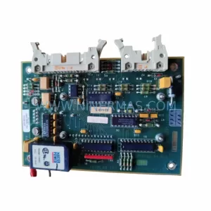
Catalog Continuation
Alternative parts within DCS Distributed Control Systems.
Stay inside the same system family when you need substitutes, adjacent modules, or a broader shortlist for procurement review.
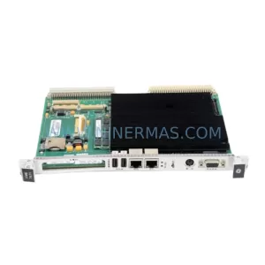
SKU: VME7671 605-064676-005 VME7671-42000A
VMIC VME7671 605-064676-005 Service-Ready Spare Part
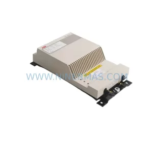
SKU: DSTC454L 5751017-R
ABB DSTC454L 5751017-R Retrofit-Compatible Fiber Optic Modem
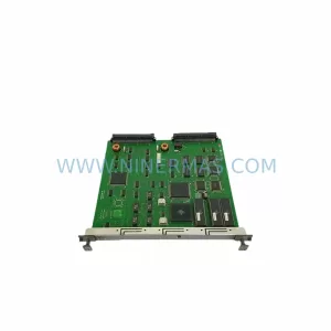
SKU: 8C-TAIDB1 8C-TAID61
Honeywell 8C-TAIDB1 Retrofit Analog Input for Legacy DCS