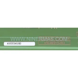
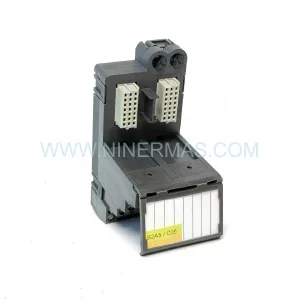
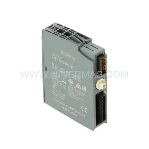
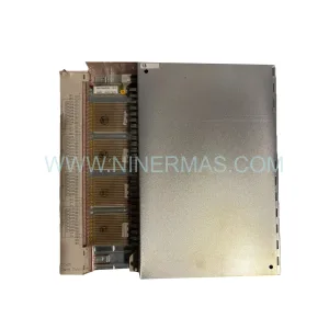
Original Industrial Spare Part
Siemens A5E00684817 Retrofit-Compatible Drive Module for Legacy Systems
Verify the part, confirm the platform family, and move straight into quotation with the right commercial details.
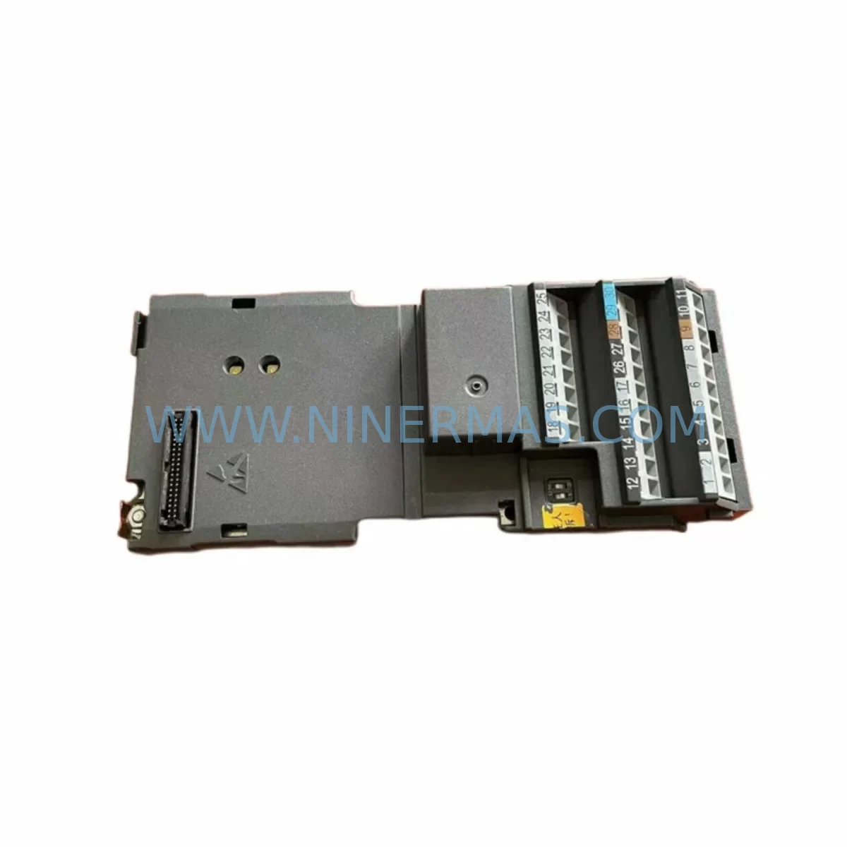
RFQ Ready
- SKUA5E00684817
- CategoryPLC & Industrial Automation Modules
- BrandSiemens
- SupportAvailability, lead time, condition, and shipping coordination
How Buyers Usually Use This Page
- Confirm the exact part number and platform family before sending the quote request.
- Use direct email when quantity, condition, and destination are already defined internally.
- Switch to the broader brand or category archive when you need alternates nearby.
Series Navigation
Move through the most common platform families behind this part.
Product RFQ
Send this part directly for quotation.
Include quantity, required condition, destination country, and target delivery timing. Current reference: Siemens A5E00684817 Retrofit-Compatible Drive Module for Legacy Systems with SKU A5E00684817.
Siemens A5E00684817 Retrofit-Compatible Drive Module for Legacy Systems
The Siemens A5E00684817 is a retrofit-compatible drive module engineered to serve as a direct replacement and upgrade solution within aging SINAMICS and MICROMASTER converter-based automation systems. As production lines built around discontinued Siemens drive platforms approach end-of-life, the A5E00684817 provides a reliable, cost-effective path to extend operational continuity without requiring a full system overhaul. NINERMAS maintains verified stock of this module, fully tested and backed by a 12-month warranty, ready for immediate dispatch to support planned maintenance windows and emergency breakdowns alike.
Industrial facilities running legacy MICROMASTER 440, MICROMASTER 420, or early-generation SINAMICS G120 control cabinets frequently encounter challenges sourcing discontinued spare parts. The A5E00684817 addresses this gap directly, offering compatibility across a range of Siemens drive families where the original module has been phased out of standard distribution channels. Engineers undertaking retrofit projects should verify the existing power supply capacity within the control cabinet before installation, as the module’s input voltage range and current draw must align with the available bus voltage on the existing backplane or mounting rail.
Upgrade Compatibility Table
| Parameter | Details |
|---|---|
| SKU / Part Number | A5E00684817 |
| Brand / Series | Siemens / SINAMICS – MICROMASTER |
| Module Function | Drive Control / Converter Interface Module |
| Mounting Interface | DIN Rail / Backplane Slot (verify existing rack dimensions) |
| Communication Compatibility | PROFIBUS DP, USS Protocol (confirm firmware revision) |
| Replacement Suitability | Direct retrofit for discontinued MICROMASTER 4xx series modules |
| Installation Space | Confirm cabinet depth and slot clearance before installation |
| Commissioning Requirement | Parameter re-upload via STARTER / SCOUT or BOP-2 operator panel |
| Warranty | 12 Months – NINERMAS Quality Assurance |
| Stock Status | Available – Ready to Ship |
Retrofit Planning for Existing Automation Systems
Successful integration of the A5E00684817 into an existing control system begins well before the module arrives on-site. Retrofit engineers should start by auditing the full drive cabinet layout, identifying the positions of the existing MICROMASTER 440 or MICROMASTER 420 drive units, the associated Control Unit (CU240E-2 or CU230P-2 variants), and any installed Power Module (PM240 or PM250) that the new module must interface with. The backplane connector pinout and slot addressing must be confirmed against the original system documentation to avoid address conflicts during startup.
Terminal wiring is a critical checkpoint. The A5E00684817 retrofit process requires engineers to map existing motor cable terminations, brake resistor connections, and safe torque off (STO) wiring against the replacement module’s terminal layout. Where the original installation used a MICROMASTER 4 series Basic Operator Panel (BOP) for local parameter access, the retrofit may require transitioning to a BOP-2 or an Intelligent Operator Panel (IOP) compatible with the updated firmware environment.
Communication protocol migration is another key consideration. Legacy systems often rely on USS protocol over RS485 for PLC-to-drive communication, while modern SINAMICS platforms favour PROFIBUS DP or PROFINET IO. If the host controller — such as a SIMATIC S7-300 or S7-400 PLC — communicates via PROFIBUS DP using a CP 342-5 communications processor, the A5E00684817 must be confirmed to support the same DP slave address and GSD file version used in the original configuration. Where protocol migration from USS to PROFIBUS is planned as part of the upgrade, the SIMATIC S7 program logic and HMI screen tag mappings on the associated SIMATIC HMI TP700 or TP900 panel must be updated to reflect the new drive parameter addresses before commissioning begins.
I/O expansion requirements should also be reviewed. If the legacy system relied on a dedicated Digital Input/Output module mounted adjacent to the drive — such as a SINAMICS G120 Terminal Module TM31 — the retrofit plan must confirm whether the TM31 remains compatible with the A5E00684817 or whether a replacement terminal module is required. Signal isolators installed between the PLC analog output and the drive frequency setpoint input should be tested for signal range compatibility, particularly where 4–20 mA current loop signals are used for speed reference.
Installation space confirmation is non-negotiable. The physical dimensions of the A5E00684817 must be measured against the available cabinet space, accounting for cable bend radius, ventilation clearance above and below the module, and the position of adjacent components such as circuit breakers, contactors, and the 24 VDC SITOP power supply unit feeding the control circuit. Where space is constrained, engineers may need to reorganise the cabinet layout or select a slimmer mounting configuration before the retrofit can proceed.
Downtime Control During System Migration
Minimising production downtime during a drive module replacement is a primary concern for any plant maintenance team. The recommended approach for A5E00684817 retrofits is to complete all pre-commissioning preparation — parameter backup, wiring documentation, spare parts staging, and HMI screen verification — during scheduled maintenance windows before the actual module swap takes place.
Parameter backup is the first protective step. Using the STARTER commissioning software or a BOP-2 operator panel, all existing drive parameters should be uploaded and saved to a project file before the old module is removed. This backup preserves motor data, ramp times, PID controller settings, and fault response configurations that would otherwise need to be re-entered manually. Where the original drive used a memory card for parameter storage, the card should be checked for compatibility with the replacement module before relying on it for parameter restore.
During the physical swap, the control circuit should remain energised where safe to do so, allowing the PLC to maintain its program execution and keep non-drive-related outputs in their last known state. The motor circuit should be isolated at the main contactor or circuit breaker, and the STO input should be verified as active before any wiring work begins. Following module installation, a controlled recommissioning sequence — motor identification run, no-load test, and loaded test at reduced speed — should be completed before returning the drive to automatic control mode. This staged approach protects the original program logic, maintains field control continuity for non-affected process loops, and reduces the risk of unplanned faults during the first production run after the retrofit.
Retrofit Support FAQ
Q: Is the A5E00684817 a direct drop-in replacement for my existing MICROMASTER module?
A: The A5E00684817 is designed as a retrofit-compatible replacement for discontinued modules within the SINAMICS and MICROMASTER converter families. Customers should confirm the exact mounting interface, terminal layout, and firmware version requirements against their existing system documentation before installation. NINERMAS technical support can assist with compatibility verification prior to order.
Q: What commissioning steps are required after installing the A5E00684817?
A: Following physical installation, the drive must be commissioned using STARTER software or a BOP-2 operator panel. This includes restoring the backed-up parameter set, running a motor identification routine, verifying communication link status on PROFIBUS DP or USS, and confirming correct operation of all digital and analog I/O signals before returning the system to automatic mode.
Q: How do I verify wiring compatibility between the A5E00684817 and my existing terminal layout?
A: Compare the terminal block layout of the A5E00684817 against the wiring diagram of the module being replaced. Pay particular attention to the STO wiring, analog input/output signal ranges, and the 24 VDC control supply connection. Where terminal positions differ, a wiring adapter or re-termination will be required. NINERMAS can provide terminal comparison documentation on request.
Q: What warranty and stock availability does NINERMAS offer for the A5E00684817?
A: NINERMAS maintains verified inventory of the A5E00684817, with each unit subject to pre-shipment functional testing. All units are covered by a 12-month warranty from the date of dispatch. Orders are processed promptly to support both planned retrofit projects and emergency breakdown requirements. Contact our team for lead time confirmation and volume pricing.
| Product Series | SINAMICS |
|---|---|
| Country of Origin | DE |
Catalog Continuation
More Siemens modules in the catalog.
Use the brand lane to compare nearby part numbers, platform-adjacent modules, and other inquiry-ready listings before sending your final RFQ.
Catalog Continuation
Alternative parts within PLC & Industrial Automation Modules.
Stay inside the same system family when you need substitutes, adjacent modules, or a broader shortlist for procurement review.