Original Industrial Spare Part
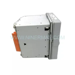
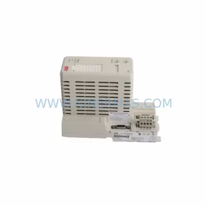
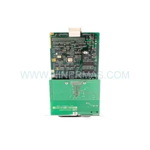
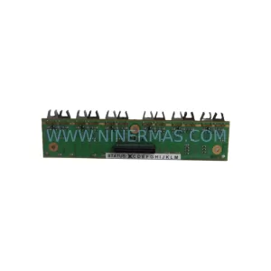
ABB AGPS21C Retrofit-Compatible Gate Power Supply for ACS Series
Verify the part, confirm the platform family, and move straight into quotation with the right commercial details.
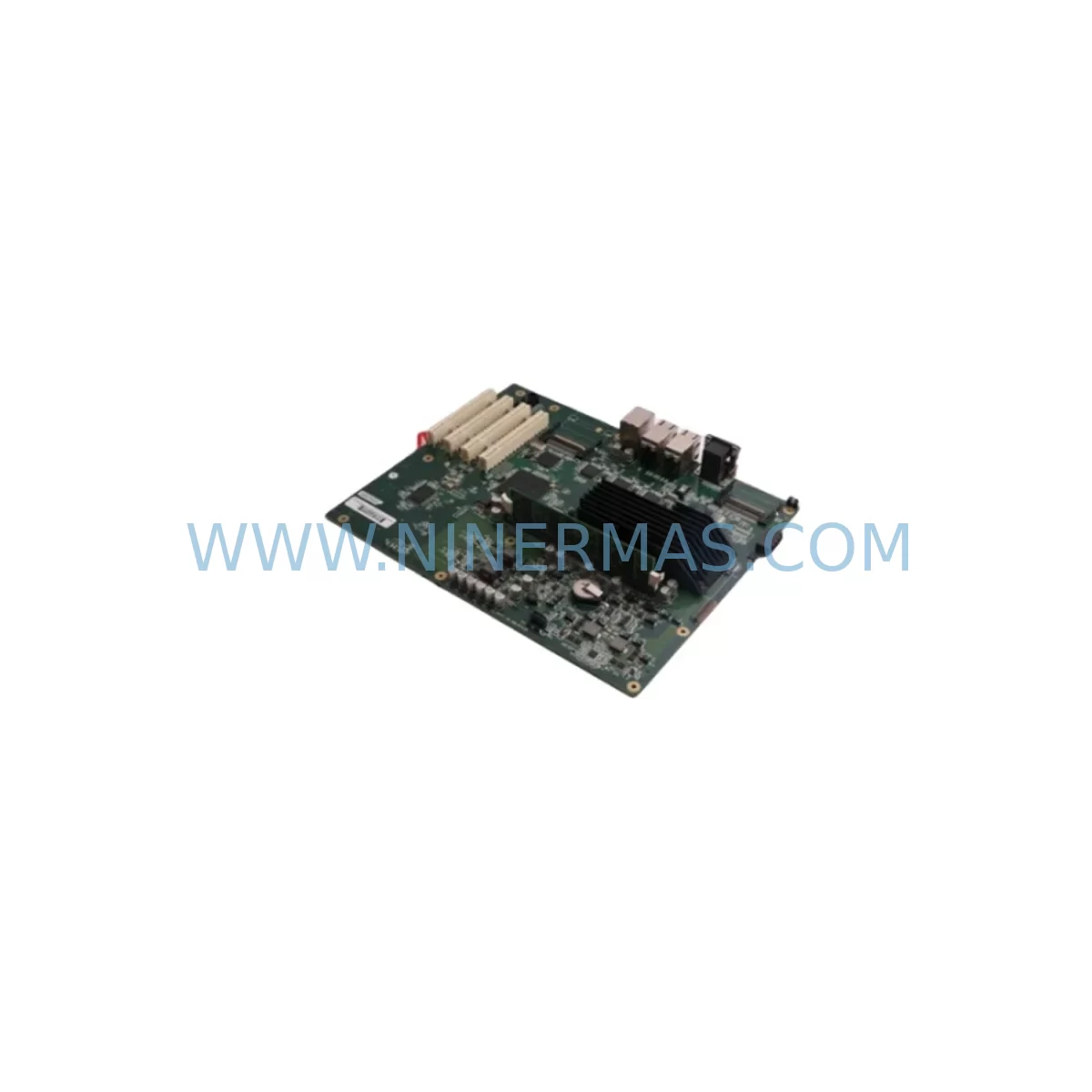
RFQ Ready
- SKUAGPS21C
- CategoryPLC & Industrial Automation Modules
- BrandABB
- SupportAvailability, lead time, condition, and shipping coordination
How Buyers Usually Use This Page
- Confirm the exact part number and platform family before sending the quote request.
- Use direct email when quantity, condition, and destination are already defined internally.
- Switch to the broader brand or category archive when you need alternates nearby.
Series Navigation
Move through the most common platform families behind this part.
Product RFQ
Send this part directly for quotation.
Include quantity, required condition, destination country, and target delivery timing. Current reference: ABB AGPS21C Retrofit-Compatible Gate Power Supply for ACS Series with SKU AGPS21C.
ABB AGPS21C Retrofit-Compatible Gate Power Supply for ACS Series
The ABB AGPS21C is a gate power supply board designed for use within ABB’s ACS series of AC drives, including the ACS600, ACS800, and related legacy inverter platforms. As these drive families approach or exceed their published end-of-life dates, plant engineers and maintenance teams face increasing pressure to source reliable replacement boards that can be installed without requiring full drive cabinet replacement or PLC reprogramming. The AGPS21C addresses this need directly: it is a retrofit-compatible component that restores gate firing capability to IGBT power modules in aging inverter assemblies, extending operational life while deferring the cost and downtime of a full system overhaul.
For facilities running continuous production lines, paper mills, water treatment stations, or material handling systems built around ABB ACS-series drives, the AGPS21C represents a cost-effective path to system recovery. Rather than replacing an entire ACS800 drive cabinet — which may involve new cable routing, updated motor protection relay settings, and HMI screen reconfiguration — maintenance teams can swap the gate power supply board, verify IGBT trigger signals with an oscilloscope, and return the drive to service within a planned maintenance window.
Upgrade Compatibility Table
| Parameter | Details |
|---|---|
| Compatible Drive Series | ABB ACS600, ACS800, ACS550 (select configurations) |
| Board Function | Gate power supply for IGBT firing circuits |
| Mounting Interface | Direct board-level replacement; matches original PCB footprint |
| Communication Compatibility | Compatible with RDCO-01/02 DDCS fiber optic communication modules |
| Power Supply Input | Verify internal DC bus auxiliary supply voltage before installation |
| Terminal Wiring | Connector pinout matches OEM specification; no rewiring required |
| Installation Space | Confirm backplane clearance and board guide rail alignment in drive frame |
| Retrofit Recommendation | Suitable for direct swap in R4–R8 frame ACS800 units |
| Commissioning Note | Run drive ID run and verify motor control parameters post-installation |
| Warranty | 12 months from date of shipment; pre-shipment functional test included |
Retrofit Planning for Existing Automation Systems
When planning a retrofit around the AGPS21C, the scope of work typically extends beyond the board itself. In an ACS800 drive cabinet, the gate power supply interfaces directly with the AINT-02 or AINT-14 inverter control board, which manages the drive’s core control logic, speed reference processing, and fault diagnostics. Before removing the failed AGPS21C, technicians should document all active fault codes from the drive’s CDP312R control panel and export the current parameter set using DriveWindow or DriveStudio software. This ensures that motor control parameters — including speed scaling, torque limits, and acceleration ramps — can be restored exactly after the board swap.
The AGPS21C also works in close proximity to the APOW-01 auxiliary power supply board, which provides low-voltage DC rails to the control electronics. If the AGPS21C has failed due to an overvoltage event or IGBT short-circuit, the APOW-01 should be inspected for secondary damage before the new board is energized. Similarly, the IOEC-04 I/O extension module — commonly used in ACS800 multi-drive systems for digital and analog I/O expansion — should be checked for communication integrity via the DDCS fiber optic ring after the board replacement is complete.
In systems where the ACS800 communicates with a higher-level PLC via a PROFIBUS-DP adapter (RPBA-01) or a DeviceNet adapter (RDNA-01), the fieldbus node address and baud rate settings stored in the drive’s parameter group 51 must be verified post-swap. A mismatch in node address or baud rate will cause the PLC to report a communication fault, which can be misdiagnosed as a hardware failure if the technician is not aware that board replacement can reset certain non-volatile parameter blocks in some firmware revisions.
For installations using an ACS800 in a master-follower configuration with a DDCS fiber optic link to a second drive unit, the fiber optic cable connections on the RDCO-01 communication module should be cleaned and re-seated during the retrofit. Contaminated fiber connectors are a common source of intermittent communication faults that surface only after a board-level repair disturbs the cable routing inside the cabinet.
Where the drive cabinet also houses an SNAT-7600 or SNAT-7610 thyristor power unit for braking or supply regeneration, the gate pulse timing relationship between the AGPS21C and the thyristor control board must be verified during commissioning. Use the drive’s built-in oscilloscope function or an external Fluke 190 series scopemeter to confirm symmetric gate pulse distribution across all six IGBT positions before running the motor under load.
Downtime Control During System Migration
Minimizing unplanned downtime is the primary concern when replacing a gate power supply board in a running production environment. The recommended approach is to pre-stage the replacement AGPS21C alongside a printed copy of the drive’s current parameter list before the maintenance window begins. If the facility operates a hot-spare drive cabinet, the parameter set can be loaded into the spare unit in advance, allowing a full cabinet swap as a fallback option if the board-level repair encounters complications.
During the board swap itself, the drive’s DC bus capacitors must be fully discharged before any internal components are touched. ABB specifies a minimum wait time of five minutes after mains disconnection for ACS800 units; in practice, technicians should verify residual voltage with a calibrated meter before proceeding. The AGPS21C is secured by a combination of PCB guide rails and a locking connector; removal requires no special tools beyond a standard ESD-safe wrist strap and a flat-blade screwdriver for the connector latch.
Once the replacement board is seated and the drive is re-energized, perform a no-load test run at low speed (5–10 Hz) before restoring the process load. Monitor the drive’s output current waveform symmetry and check for any residual fault codes on the CDP312R panel. If the drive was previously running a motor ID run, re-execute the ID run to ensure the motor model is correctly calibrated to the new gate timing characteristics. This step is particularly important in applications with high dynamic torque demands, such as winders, cranes, or centrifuges.
By following a structured pre-staging and commissioning checklist, most AGPS21C replacements can be completed within a two-to-four-hour planned maintenance window, preserving production continuity and avoiding the extended lead times associated with full drive replacement.
Retrofit Support FAQ
Q: Is the AGPS21C a direct drop-in replacement for the original board in my ACS800?
A: Yes, for R4–R8 frame ACS800 units, the AGPS21C is a direct board-level replacement. The PCB footprint, connector pinout, and mounting guide rails match the OEM specification. No wiring modifications are required. Confirm your drive’s frame size and internal revision label before ordering to ensure compatibility with your specific cabinet configuration.
Q: Does each unit undergo functional testing before shipment?
A: Yes. Every AGPS21C unit is subject to pre-shipment functional testing to verify gate pulse output, auxiliary power rail integrity, and connector continuity. A test record is retained for each unit. The board ships with a 12-month warranty covering manufacturing defects and functional failures under normal operating conditions.
Q: What should I check if the drive faults immediately after installing the replacement AGPS21C?
A: First, verify that the DC bus auxiliary supply voltage is within specification before the board powers up. Check that all fiber optic connections on the RDCO-01 module are clean and fully seated. Confirm that the AINT control board firmware version is compatible with the AGPS21C revision installed. If fault code 0022 (gate power supply fault) persists, inspect the IGBT power module for internal short-circuit damage that may have caused the original board failure.
Q: Can you supply the AGPS21C for older ACS600 installations?
A: Stock availability for ACS600-compatible configurations is maintained on a best-effort basis given the age of the platform. Contact our sales team at sale@ninermas.com to confirm current inventory and lead time. For ACS600 systems, also consider whether the AINT-02 control board and APOW-01 auxiliary power supply are still serviceable, as these components are equally subject to age-related failure in long-running installations.
| Product Series | ACS |
|---|---|
| Country of Origin | SE |
Catalog Continuation
More ABB modules in the catalog.
Use the brand lane to compare nearby part numbers, platform-adjacent modules, and other inquiry-ready listings before sending your final RFQ.
SKU: CI532V02 3BSE003827R1
ABB CI532V02 3BSE003827R1 Safety-Reliable MODBUS Module
SKU: ZCU-14 3AXD50000005164
ABB ZCU-14 3AXD50000005164 Safety-Reliable Drive Control Unit
SKU: DSPU131 3BSE000355R1
ABB DSPU131 3BSE000355R1 Safety-Reliable DSP Unit for Critical Control
Catalog Continuation
Alternative parts within PLC & Industrial Automation Modules.
Stay inside the same system family when you need substitutes, adjacent modules, or a broader shortlist for procurement review.