Original Industrial Spare Part
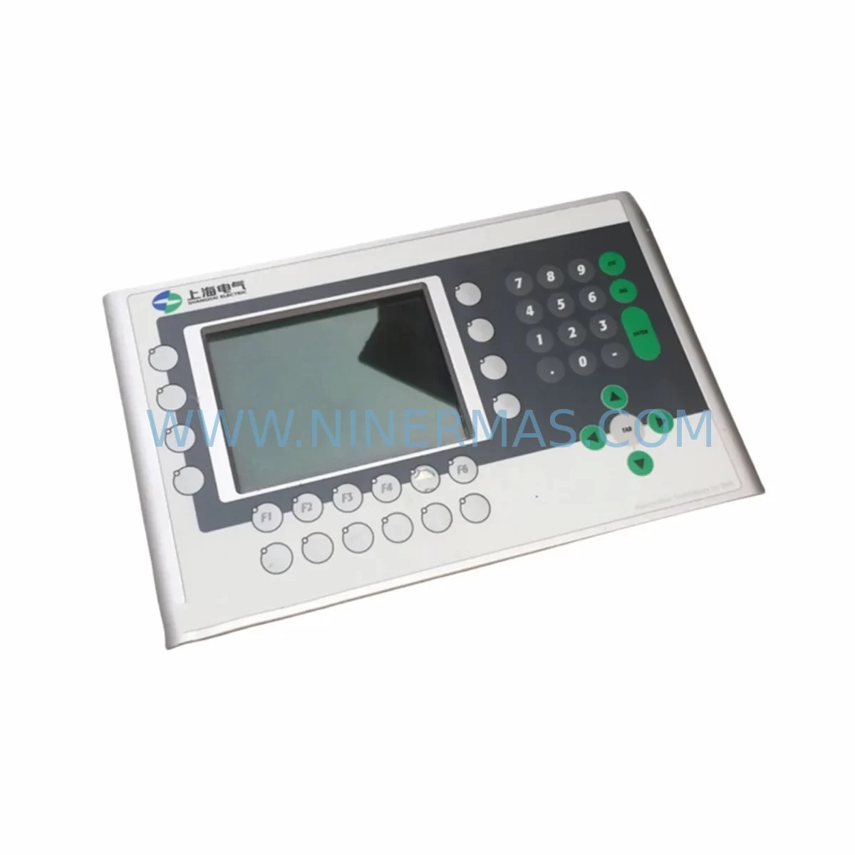
B&R 4PP350.0571-K01 Retrofit-Compatible HMI Panel for Legacy Systems
Verify the part, confirm the platform family, and move straight into quotation with the right commercial details.
RFQ Ready
- SKU4PP350.0571-K01
- CategoryPLC & Industrial Automation Modules
- BrandB&R
- SupportAvailability, lead time, condition, and shipping coordination
How Buyers Usually Use This Page
- Confirm the exact part number and platform family before sending the quote request.
- Use direct email when quantity, condition, and destination are already defined internally.
- Switch to the broader brand or category archive when you need alternates nearby.
Series Navigation
Move through the most common platform families behind this part.
Product RFQ
Send this part directly for quotation.
Include quantity, required condition, destination country, and target delivery timing. Current reference: B&R 4PP350.0571-K01 Retrofit-Compatible HMI Panel for Legacy Systems with SKU 4PP350.0571-K01.
B&R 4PP350.0571-K01 Retrofit-Compatible HMI Panel for Legacy Systems
The B&R 4PP350.0571-K01 is a ruggedized industrial HMI touch panel engineered for demanding automation environments. As legacy B&R Power Panel and 4PP-series installations approach end-of-life, the 4PP350.0571-K01 serves as a direct retrofit replacement, enabling control system modernization without requiring a full PLC or cabinet redesign. Its compact form factor, wide operating temperature range, and compatibility with B&R Automation Studio programming environments make it a preferred choice for engineers managing aging production lines, control cabinet upgrades, and distributed I/O migrations.
Whether you are replacing a failed 4PP120, 4PP220, or 4PP320 panel in an existing machine frame, or upgrading a legacy SDRAM-based HMI to a modern flash-storage platform, the 4PP350.0571-K01 provides a reliable migration path with minimal downtime exposure. Its panel cutout dimensions and mounting hole pattern are designed to align with previous-generation B&R Power Panel installations, reducing mechanical rework during retrofit projects.
Upgrade Compatibility Table
| Parameter | Detail |
|---|---|
| SKU / Part Number | 4PP350.0571-K01 |
| Brand / Manufacturer | B&R Industrial Automation |
| Series | 4PP350 Power Panel |
| Display Size | 5.7-inch TFT LCD Touch Screen |
| Resolution | 320 × 240 (QVGA) |
| Operating Temperature | 0 °C to +50 °C (panel face); storage –20 °C to +60 °C |
| Protection Rating | IP65 front panel (NEMA 4X equivalent) |
| Power Supply Input | 24 V DC (nominal); verify existing cabinet PSU capacity before swap |
| Communication Interfaces | Ethernet (10/100 Mbit), RS232/RS485, CAN, USB |
| Programming Environment | B&R Automation Studio 3.x / 4.x compatible |
| Typical Legacy Replacements | 4PP120.0571-K01, 4PP220.0571-K01, 4PP320.0571-K01 |
| Mounting | Panel cutout mount; VESA-compatible adapter available |
| Retrofit Wiring Adaptation | Terminal block pinout review required; X2X Link or POWERLINK backplane check recommended |
| Commissioning Notes | Re-map node address; reload Automation Studio project; verify HMI visualization pages |
| Warranty | 12 Months — covers manufacturing defects; pre-shipment functional test included |
Retrofit Planning for Existing Automation Systems
Successful integration of the 4PP350.0571-K01 into an existing B&R automation architecture begins with a thorough audit of the current control cabinet. Engineers should first confirm that the 24 V DC power supply — typically a B&R PS3100 or equivalent third-party DIN-rail PSU — can sustain the additional current draw of the replacement panel without tripping overcurrent protection. In many legacy installations, the original PSU was sized tightly for the 4PP120 or 4PP220 series, and a capacity margin check is essential before energizing the new unit.
Terminal block wiring is the next critical checkpoint. The 4PP350.0571-K01 uses a standardized connector layout, but field wiring routed to older X20 I/O modules or X67 distributed I/O nodes may require adapter harnesses or re-termination at the cabinet backplane. If the existing system uses X20CP1301 or X20CP3485 CPUs communicating over X2X Link, the new panel must be assigned a unique node address within the X2X segment to avoid address conflicts that can prevent the CPU from recognizing the HMI at startup.
For installations running POWERLINK as the real-time Ethernet backbone — common in multi-axis motion control cells using ACOPOS or ACOPOSmulti servo drives — the 4PP350.0571-K01 must be configured as a POWERLINK Managing Node (MN) or Controlled Node (CN) depending on the network topology. Verify that the Automation Studio project’s hardware configuration reflects the correct node number and that the POWERLINK cycle time is compatible with the panel’s communication stack version.
Where the legacy system relied on RS232 or RS485 serial links to third-party instruments, barcode readers, or weighing terminals, the 4PP350.0571-K01’s onboard COM ports provide a direct replacement path. However, baud rate, parity, and stop-bit settings stored in the original Automation Studio project must be preserved and re-validated after the panel swap. If the original HMI communicated with a Modbus RTU slave network, the serial driver configuration in the new panel’s runtime must be re-initialized before the first production run.
Panel-mounted B&R 4AC power supply modules and 4TB terminal block assemblies installed in the same cabinet should be inspected for wear and contact oxidation during the retrofit window. Replacing these passive components alongside the HMI panel reduces the risk of nuisance faults after recommissioning. Similarly, if the cabinet houses a B&R 4IF Fieldbus Interface or a legacy PROFIBUS DP coupler, confirm that the new panel’s firmware supports the same GSD file version used by the field devices on the bus.
For systems where the original HMI visualization was developed in B&R VC4 (Visual Components 4) or an earlier mapp View project, the project archive should be backed up to a USB drive or network share before the panel is removed. The 4PP350.0571-K01 supports mapp View 5.x web-based visualization, which may require a project migration step in Automation Studio if the source project was built on an older VC4 framework. Allocate time in the retrofit schedule for HMI screen validation, alarm list review, and operator acceptance testing before returning the line to production.
Downtime Control During System Migration
Minimizing unplanned downtime is the primary concern for any control system retrofit. When replacing the 4PP350.0571-K01 in a live production environment, the recommended approach is to pre-configure the replacement panel offline using a development PC running Automation Studio, with the target hardware configuration set to match the existing system’s CPU type, I/O map, and communication parameters. This offline preparation allows the physical swap to be completed within a single planned maintenance window — typically two to four hours for a straightforward panel replacement — rather than requiring extended troubleshooting on the factory floor.
Before powering down the cabinet, export the current Automation Studio project from the running CPU using the online transfer function, and save a full backup of the HMI runtime data, recipe files, and alarm history to removable storage. If the system uses a B&R X20 data logger or a third-party SCADA historian, confirm that all process data has been flushed and archived before the shutdown sequence begins.
During the physical swap, label all field wiring at the terminal blocks before disconnection, and photograph the original wiring layout for reference during reconnection. After installing the 4PP350.0571-K01 and restoring the Automation Studio project, perform a cold start of the CPU and monitor the system diagnostic log for any I/O module errors, communication timeouts, or address conflicts. Validate all HMI screens, setpoint entries, and alarm acknowledgment functions before releasing the system to operators. A structured commissioning checklist — covering power-on sequence, communication link verification, I/O force test, and HMI screen navigation — reduces the risk of overlooked faults and supports a confident handover to production staff.
Retrofit Support FAQ
Q1: Is the 4PP350.0571-K01 a direct drop-in replacement for the 4PP220.0571-K01?
In most cases, yes. The panel cutout dimensions and 24 V DC power input are compatible. However, you should verify the Automation Studio hardware configuration and update the target CPU’s hardware tree to reference the 4PP350 module. HMI visualization projects may require a minor migration step if originally developed on VC4.
Q2: What commissioning steps are required after installation?
After physical installation, assign the correct node address, download the Automation Studio project to the CPU, and perform a full I/O force test to confirm all digital and analog signals are mapped correctly. Validate all HMI screens and communication links (Ethernet, RS232/RS485, CAN) before returning to production. Pre-shipment functional testing is completed at our facility prior to dispatch.
Q3: How is wiring compatibility handled when replacing an older 4PP-series panel?
The 4PP350.0571-K01 uses standard B&R terminal block connectors. In most retrofit scenarios, existing field wiring can be re-terminated directly. Where connector pinouts differ from the legacy panel, a short adapter harness is sufficient. Always cross-reference the original wiring diagram against the 4PP350 hardware manual before reconnection.
Q4: What does the 12-month warranty cover, and is stock available?
The 12-month warranty covers manufacturing defects and functional failures under normal operating conditions. Every unit undergoes pre-shipment functional testing before dispatch. Stock is maintained for prompt order fulfillment. Contact our team for lead time confirmation and volume pricing.
| Product Series | Legacy |
|---|---|
| Country of Origin | AT |
Catalog Continuation
More B&R modules in the catalog.
Use the brand lane to compare nearby part numbers, platform-adjacent modules, and other inquiry-ready listings before sending your final RFQ.
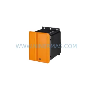
SKU: 8BVI0220HCD8.000-1
B&R 8BVI0220HCD8.000-1 Retrofit-Compatible Servo Drive for Legacy Systems
SKU: 5PC910.SX05-00
B&R 5PC910.SX05-00 Retrofit Industrial PC for Legacy Systems
Catalog Continuation
Alternative parts within PLC & Industrial Automation Modules.
Stay inside the same system family when you need substitutes, adjacent modules, or a broader shortlist for procurement review.
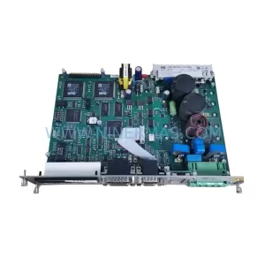
SKU: DSC2P142-111-000
Etel DSC2P142-111-000 Retrofit-Compatible Digital Servo Amplifier
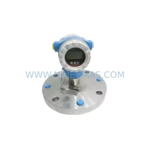
SKU: FMB51-AA21RA1FGC80GGJB3A+AA
E+H FMB51-AA21RA1FGC80GGJB3A+AA Retrofit Magnetic Flowmeter