Original Industrial Spare Part
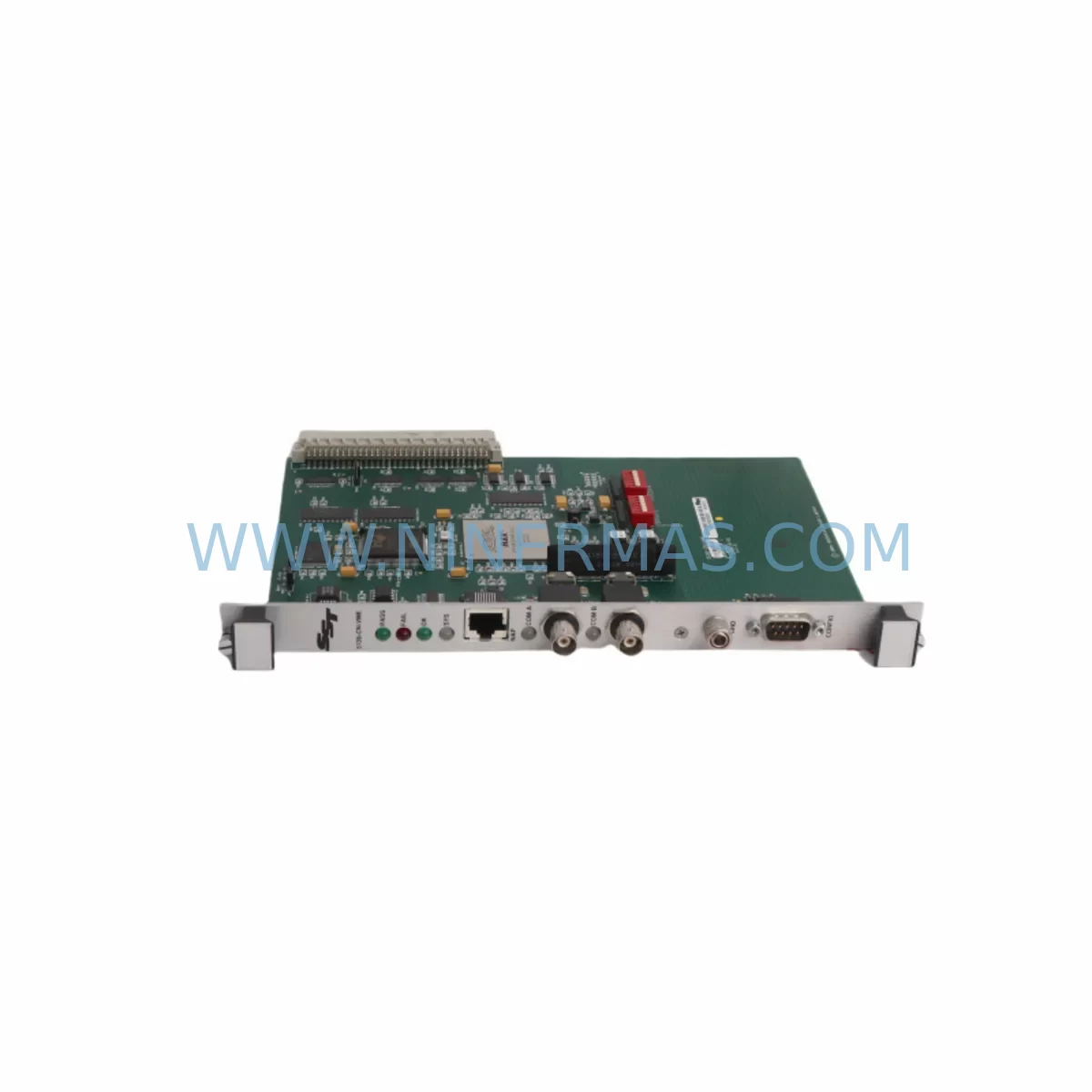
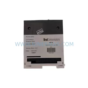
MOLEX 5136-CN-VME Retrofit-Compatible VME Interface Module
Verify the part, confirm the platform family, and move straight into quotation with the right commercial details.
RFQ Ready
- SKU5136-CN-VME
- CategoryPLC & Industrial Automation Modules
- BrandMolex
- SupportAvailability, lead time, condition, and shipping coordination
How Buyers Usually Use This Page
- Confirm the exact part number and platform family before sending the quote request.
- Use direct email when quantity, condition, and destination are already defined internally.
- Switch to the broader brand or category archive when you need alternates nearby.
Series Navigation
Move through the most common platform families behind this part.
Product RFQ
Send this part directly for quotation.
Include quantity, required condition, destination country, and target delivery timing. Current reference: MOLEX 5136-CN-VME Retrofit-Compatible VME Interface Module with SKU 5136-CN-VME.
MOLEX 5136-CN-VME Retrofit-Compatible VME Interface Module for Legacy System Modernization
The MOLEX 5136-CN-VME is a ruggedized VME (Versa Module Europa) interface module engineered for demanding industrial environments where signal integrity, mechanical durability, and long-term supply continuity are non-negotiable. As legacy VME-based control architectures approach end-of-life, the 5136-CN-VME has become a critical retrofit component for system integrators and plant engineers tasked with extending the operational lifespan of existing automation platforms without full system replacement.
Designed to operate reliably in high-vibration, wide-temperature, and EMI-intensive environments, the 5136-CN-VME supports seamless integration into existing VME backplane architectures. Its ruggedized connector interface ensures stable signal transmission across the VME bus, making it a preferred choice for aerospace ground support, defense electronics, industrial process control, and transportation automation systems where downtime is measured in production losses and safety risk.
Upgrade Compatibility Table
| Parameter | Details |
|---|---|
| SKU / Part Number | 5136-CN-VME |
| Brand / Manufacturer | MOLEX |
| Series | 5136 VME Connector Series |
| Interface Standard | VMEbus (IEEE 1014 / IEC 821) |
| Connector Type | DIN 41612 Ruggedized VME Backplane Interface |
| Installation Format | Standard VME 6U / 3U Backplane Slot Compatible |
| Operating Temperature | -40°C to +85°C (ruggedized grade) |
| Vibration Resistance | MIL-STD-810 / IEC 60068-2-6 compliant (inferred) |
| Communication Compatibility | VMEbus, VME64, VME64x backplane protocols |
| Replacement Suitability | Direct retrofit for legacy VME interface connectors in 5136 series footprint |
| Debugging Focus | Backplane seating torque, pin alignment, bus termination verification |
| Warranty | 12 Months — All units pre-shipment tested and documented |
| Availability | In Stock — Long-term supply program supported |
Retrofit Planning for Existing Automation Systems
When planning a VME-based system retrofit, the 5136-CN-VME typically enters the workflow at the connector and backplane interface layer — the physical foundation that all other modules depend on. Before installation, engineers must confirm that the existing VME backplane (whether a 6U or 3U form factor) provides the correct slot pitch and DIN 41612 receptacle alignment. In many legacy control cabinets, the backplane itself may be a SCHROFF or Elma VME chassis, and the 5136-CN-VME’s ruggedized shell is designed to mate reliably with these standard VME rack systems without requiring chassis modification.
In a typical retrofit scenario, the 5136-CN-VME is installed alongside or as a replacement for aging VME CPU boards, I/O modules, and communication cards. For example, when replacing a legacy Motorola MVME162 or MVME2700 single-board computer, the interface connector integrity is the first checkpoint — a worn or intermittent VME connector is often the root cause of unexplained bus errors, module dropouts, and CRC faults that are misdiagnosed as CPU or memory failures. Replacing the 5136-CN-VME connector assembly restores reliable bus communication before the new SBC is seated.
Power supply compatibility is another critical pre-retrofit checkpoint. VME systems typically operate on ±5V, ±12V rails supplied by a dedicated VME power supply module. Before installing the 5136-CN-VME, verify that the existing power supply — such as a Vicor or Elma VME power module — delivers stable rail voltages within VMEbus specification tolerances. Voltage sag on the +5V rail is a common cause of connector contact degradation in high-cycle VME systems.
For systems incorporating VME-to-serial or VME-to-Ethernet communication bridges — such as a GreenSpring IP-Octal or a Dy-4 Systems SVME/DMV-183 communications module — the 5136-CN-VME retrofit must be coordinated with a bus continuity check to ensure that the communication module’s interrupt lines and address decoding remain intact after connector replacement. In protocol migration projects moving from RS-232 or MIL-STD-1553 to Ethernet-based SCADA links, the VME backplane connector is the physical anchor point for all signal routing, and its integrity directly affects protocol transition success.
I/O expansion cards — including analog input modules, digital output modules, and signal conditioning boards from manufacturers such as Acromag, SBS Technologies, or Radstone — must be re-seated and re-addressed after any VME connector replacement. Module address switches and jumper settings should be documented before disassembly and verified against the system’s address map after reinstallation. HMI screens connected via VME-resident display controllers should be tested for screen refresh continuity and alarm acknowledgment response after the retrofit to confirm that the operator interface layer has not been disrupted.
For systems using VME-based programmable logic controllers or motion controllers, the program logic stored in battery-backed SRAM or flash memory on the CPU board must be backed up before any connector work begins. A portable programming cable — such as a Motorola BDM debug cable or a JTAG interface — should be used to verify program integrity post-installation. This step is especially important in legacy discrete manufacturing lines where the PLC ladder logic has not been formally documented and exists only in the controller’s onboard memory.
Downtime Control During System Migration
Minimizing unplanned downtime during a VME connector retrofit requires a structured pre-outage preparation protocol. The first step is a full system image backup: all CPU board memory contents, I/O module configurations, and communication parameter tables should be captured using the appropriate programming tool before the maintenance window begins. For VME systems integrated with SCADA platforms via OPC-DA or Modbus TCP, the SCADA historian should be placed in manual data entry mode to preserve data continuity during the outage.
The physical replacement of the 5136-CN-VME connector assembly should be performed with the VME chassis fully de-energized and the backplane bus discharged. Anti-static precautions — grounding straps, ESD mats, and humidity-controlled work areas — are mandatory for ruggedized VME connector work, as electrostatic discharge can damage the gold-plated contact surfaces that are critical for low-resistance bus connections.
After installation, a structured power-up sequence should be followed: power supply rails first, then backplane bus termination verification, then individual module insertion in address order. Bus analyzers — such as a Vmetro BT33 or equivalent VMEbus protocol analyzer — can be used to confirm that the 5136-CN-VME connector is delivering clean bus cycles before the full system is brought online. This staged power-up approach reduces the risk of cascading faults and allows each module to be individually validated before the system is returned to production.
For continuous-process industries where even a brief control interruption is unacceptable, a hot-standby VME chassis with a pre-configured spare 5136-CN-VME can be used to achieve near-zero-downtime switchover. The standby chassis is pre-loaded with the current program image and I/O configuration, and the switchover is executed as a controlled transfer rather than an emergency replacement. This approach is particularly effective in chemical processing, power generation, and water treatment applications where the VME-based DCS or SCADA system is the primary process control layer.
Retrofit Support FAQ
Q1: Is the MOLEX 5136-CN-VME a direct drop-in replacement for other VME interface connectors in the 5136 series?
A: The 5136-CN-VME is designed to the DIN 41612 VMEbus connector standard and is mechanically and electrically compatible with standard VME 6U and 3U backplane slots. It is a direct retrofit replacement for legacy 5136-series connectors in the same footprint. Minor differences in shell plating or contact material between production batches may require a contact resistance verification after installation, which is standard practice for any VME connector replacement.
Q2: What pre-shipment testing is performed on the 5136-CN-VME before delivery?
A: Every unit undergoes contact continuity testing, insulation resistance measurement, and mechanical insertion/extraction force verification before shipment. Test records are available upon request. All units are shipped in ESD-protective packaging with humidity indicator cards to ensure connector contact integrity during transit.
Q3: How do I verify wiring and termination compatibility during installation?
A: Before installation, compare the existing backplane connector pinout against the 5136-CN-VME datasheet to confirm row A, B, and C contact assignments match your system’s VMEbus wiring. For VME64 or VME64x systems with P2 connector extensions, verify that the extended row assignments are compatible with your I/O module’s rear-panel transition card. A continuity check between the backplane connector and the chassis ground plane should be performed after installation to confirm proper shielding.
Q4: What is the warranty coverage and what does it include?
A: The MOLEX 5136-CN-VME is covered by a 12-month warranty from the date of shipment. The warranty covers manufacturing defects, contact failure under normal operating conditions, and mechanical integrity of the connector housing. It does not cover damage resulting from improper installation, ESD events, or operation outside the specified environmental ratings. Warranty claims are processed with a replacement unit dispatched within 5 business days of fault confirmation.
| Product Series | Other series |
|---|
Catalog Continuation
More Molex modules in the catalog.
Use the brand lane to compare nearby part numbers, platform-adjacent modules, and other inquiry-ready listings before sending your final RFQ.
Catalog Continuation
Alternative parts within PLC & Industrial Automation Modules.
Stay inside the same system family when you need substitutes, adjacent modules, or a broader shortlist for procurement review.