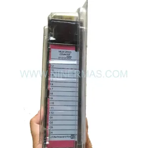
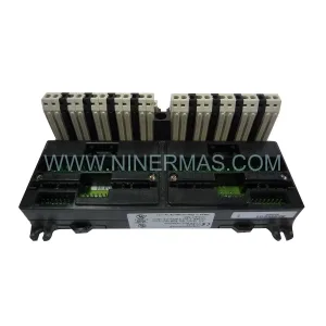
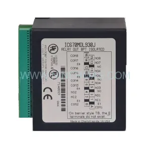
Original Industrial Spare Part
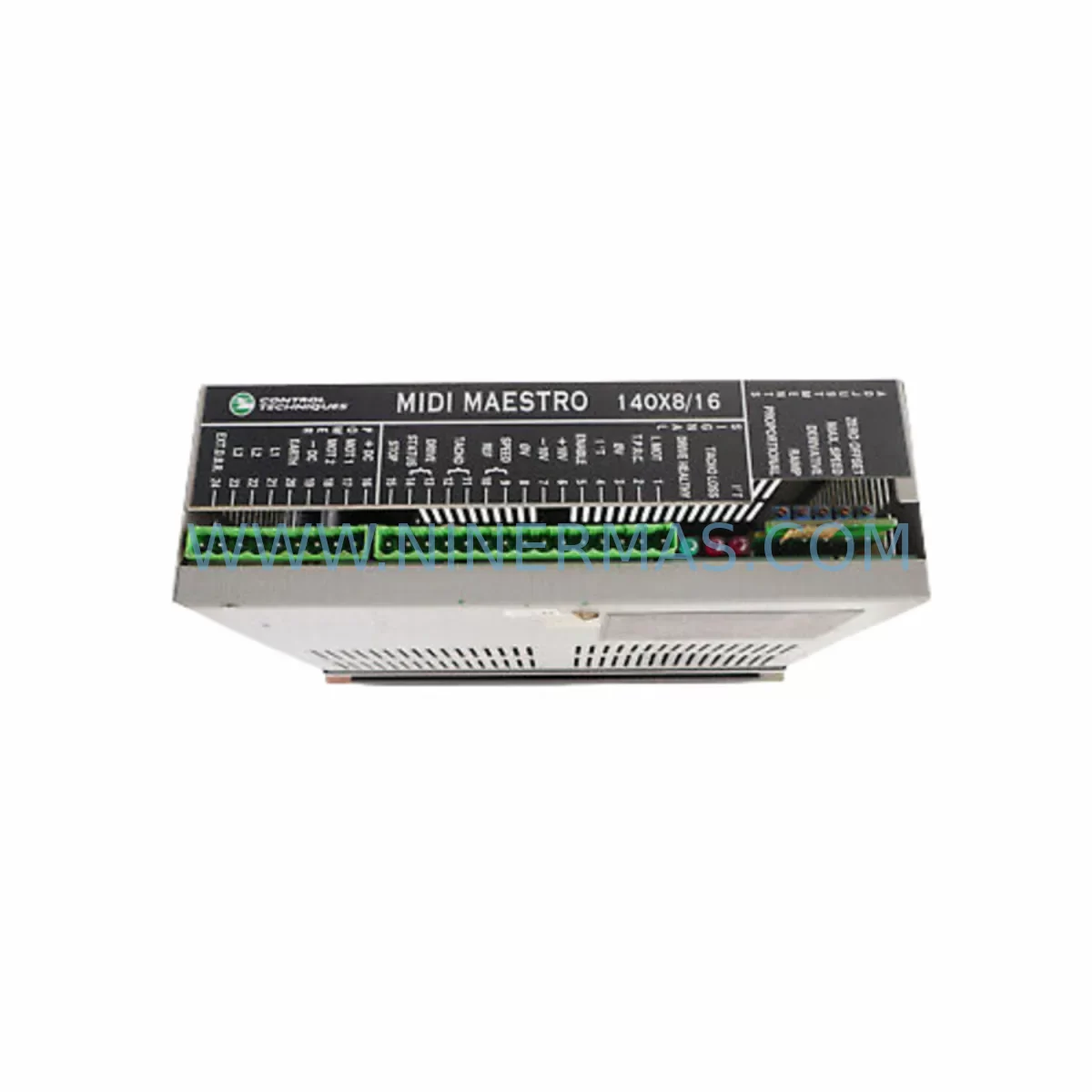
Control Techniques MAESTRO 140X8/16 Retrofit Servo Drive
Verify the part, confirm the platform family, and move straight into quotation with the right commercial details.
RFQ Ready
- SKUMAESTRO 140X8/16
- CategoryPLC & Industrial Automation Modules
- BrandControl Techniques
- SupportAvailability, lead time, condition, and shipping coordination
How Buyers Usually Use This Page
- Confirm the exact part number and platform family before sending the quote request.
- Use direct email when quantity, condition, and destination are already defined internally.
- Switch to the broader brand or category archive when you need alternates nearby.
Series Navigation
Move through the most common platform families behind this part.
Product RFQ
Send this part directly for quotation.
Include quantity, required condition, destination country, and target delivery timing. Current reference: Control Techniques MAESTRO 140X8/16 Retrofit Servo Drive with SKU MAESTRO 140X8/16.
Control Techniques MAESTRO 140X8/16 Retrofit Servo Drive: Legacy-Compatible Upgrade for Industrial Automation
The Control Techniques MAESTRO 140X8/16 is a high-performance servo drive designed for precision motion control in demanding industrial environments. As legacy automation systems age and original equipment manufacturers discontinue support for older drive platforms, the MAESTRO 140X8/16 has become a critical retrofit component for engineers tasked with modernizing control cabinets, extending production line lifecycles, and maintaining operational continuity without full system replacement.
This unit supports a wide range of servo motor configurations and is engineered for compatibility with legacy Control Techniques motion platforms. Whether you are replacing a failed drive in an existing MAESTRO-series rack or upgrading from an earlier-generation servo amplifier, the MAESTRO 140X8/16 provides a reliable, tested, and immediately deployable solution. Each unit supplied by NINERMAS undergoes pre-shipment functional testing and is backed by a 12-month warranty, ensuring confidence in every deployment.
Upgrade Compatibility Table
| Parameter | MAESTRO 140X8/16 Details |
|---|---|
| Series | Control Techniques MAESTRO |
| Form Factor | Rack-mount module (MAESTRO backplane compatible) |
| Axis Configuration | 8/16 axis servo drive module |
| Communication Interface | Proprietary MAESTRO backplane bus; compatible with CT motion network |
| Replacement Compatibility | Direct replacement for MAESTRO 140X8/16 in existing racks; verify backplane slot addressing |
| Installation Requirement | Confirm rack slot dimensions, backplane connector alignment, and module address DIP settings |
| Power Supply Compatibility | Verify MAESTRO PSU capacity (e.g., MAESTRO 140CPU11302 or equivalent power module) |
| Commissioning Tool | Control Techniques CTSoft or MAESTRO Toolkit; verify firmware version compatibility |
| Warranty | 12 months from date of shipment |
| Pre-Shipment Test | Yes — functional verification performed before dispatch |
Retrofit Planning for Existing Automation Systems
Integrating the MAESTRO 140X8/16 into an existing control architecture requires careful pre-installation planning. Engineers should begin by auditing the current rack configuration, confirming available backplane slots, and verifying that the MAESTRO power supply module — such as the MAESTRO 140CPS11400 or a compatible PSU variant — can support the additional axis load introduced by the replacement drive. Insufficient power headroom is one of the most common causes of instability during servo drive retrofits.
Terminal wiring must be mapped against the original installation drawings. The MAESTRO 140X8/16 uses a defined connector pinout for motor feedback, encoder signals, and enable/inhibit lines. If the original wiring harness was built for an earlier MAESTRO axis module, verify that the feedback cable — typically a 15-pin D-sub or equivalent — matches the replacement unit’s encoder interface. Mismatched feedback wiring is a frequent source of fault codes during initial commissioning.
Backplane slot addressing is critical. The MAESTRO system assigns axis identities based on physical slot position and DIP switch or rotary address settings on the module itself. Before powering the system, confirm that the module address matches the axis definition in the motion program stored on the MAESTRO 140CPU controller. A mismatch will prevent the axis from being recognized and may trigger a system fault that halts all motion.
For systems that also include MAESTRO 140XTS expansion modules, MAESTRO 140ACI analog input cards, or MAESTRO 140NOM network option modules, the retrofit scope may extend beyond the servo drive itself. Communication links between the MAESTRO controller and upstream SCADA or DCS platforms — often using Modbus RTU, Profibus DP, or DeviceNet — should be verified to remain intact after the drive swap. If the original drive carried axis-specific parameters in non-volatile memory, those parameters must be re-entered or downloaded from a backup before the axis is enabled.
HMI screens tied to axis status, drive fault codes, or position feedback should be reviewed after commissioning. Operator panels connected via the MAESTRO system — or via a separate Unidrive SP or Digitax ST drive on the same control network — may display axis-specific data that requires re-mapping if the replacement module reports slightly different status word structures. Coordinate with the HMI programmer to validate all relevant screen objects before returning the line to production.
Where I/O expansion is part of the retrofit scope, MAESTRO 140DDI digital input modules and MAESTRO 140DDO digital output modules should be inventoried alongside the servo drive replacement. A complete retrofit often involves refreshing multiple rack components simultaneously to avoid returning to the cabinet for secondary failures within a short interval after the initial repair.
Downtime Control During System Migration
Minimizing unplanned downtime during a MAESTRO 140X8/16 replacement requires a structured migration approach. Begin by creating a full backup of the motion program from the MAESTRO 140CPU controller using CTSoft or the MAESTRO Toolkit before any hardware is disturbed. Store the backup on at least two independent media — a local engineering laptop and a network drive — to protect against data loss during the physical swap.
Where possible, perform the drive replacement during a scheduled maintenance window rather than in response to an emergency failure. Emergency replacements under production pressure increase the risk of wiring errors, incorrect address settings, and incomplete commissioning. A planned replacement allows time to bench-test the new MAESTRO 140X8/16 unit against a known-good motor before installation, confirming that the drive responds correctly to enable signals and produces the expected torque and velocity profiles.
During the physical swap, label all connectors and cables before disconnection. Photograph the original wiring configuration from multiple angles. If the system uses a MAESTRO 140CRP Compact Remote I/O module or remote axis nodes connected via the MAESTRO motion bus, confirm that the bus termination resistors remain correctly positioned after the drive is removed and replaced.
After installation, perform a controlled power-up sequence: apply control power first, verify that the MAESTRO CPU recognizes the new axis module, then apply motor power and execute a low-speed jog move before returning the axis to automatic mode. Monitor drive status LEDs and the CPU diagnostic display throughout. Document the commissioning result and update the site maintenance record to reflect the replacement date, unit serial number, and any parameter changes made during the process.
By following this structured approach, most MAESTRO 140X8/16 replacements can be completed within a single shift, keeping production interruption to a minimum and ensuring that the restored axis performs to the original specification.
Retrofit Support FAQ
Q1: Is the MAESTRO 140X8/16 a direct drop-in replacement for the original unit?
In most cases, yes. The MAESTRO 140X8/16 is designed to fit the standard MAESTRO rack backplane and uses the same connector interface as the original module. However, you should verify the module address settings (DIP switches or rotary selectors) match the axis assignment in your motion program, and confirm that your MAESTRO power supply has sufficient capacity to support the axis load. Minor firmware differences between production batches may require a parameter download from your backup file before the axis operates correctly.
Q2: What commissioning steps are required after installation?
After seating the module in the rack and confirming address settings, restore axis parameters from your CTSoft or MAESTRO Toolkit backup. Apply control power and verify that the MAESTRO 140CPU recognizes the axis. Apply motor power and perform a low-speed jog to confirm encoder feedback and torque response. Check all HMI status displays and I/O interlocks before returning the axis to automatic mode. If the system includes a Unidrive SP or Digitax ST on the same network, verify that inter-drive communication remains stable.
Q3: Does the unit come with a warranty and pre-shipment testing?
Yes. Every MAESTRO 140X8/16 supplied by NINERMAS is functionally tested before dispatch and covered by a 12-month warranty from the date of shipment. If the unit develops a fault within the warranty period under normal operating conditions, we will provide a replacement or repair at no additional cost. Contact sale@ninermas.com with your order reference and fault description to initiate a warranty claim.
Q4: What is the typical lead time and stock availability?
We maintain stock of the MAESTRO 140X8/16 and related MAESTRO-series components to support urgent retrofit and breakdown requirements. Standard orders are dispatched within 1–3 business days. For large-quantity orders or projects requiring multiple MAESTRO axis modules, power supplies, or CPU units, contact our sales team in advance to confirm availability and reserve stock. We can also source related components such as MAESTRO 140XTS expansion modules, 140ACI analog cards, and compatible programming cables to support a complete retrofit package.
| Product Series | Other series |
|---|
Catalog Continuation
More Control Techniques modules in the catalog.
Use the brand lane to compare nearby part numbers, platform-adjacent modules, and other inquiry-ready listings before sending your final RFQ.

Catalog Continuation
Alternative parts within PLC & Industrial Automation Modules.
Stay inside the same system family when you need substitutes, adjacent modules, or a broader shortlist for procurement review.
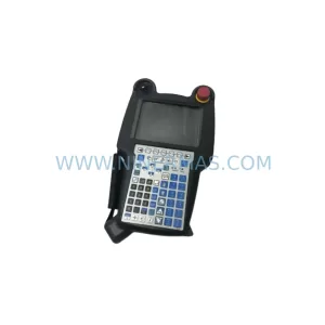
SKU: A05B-2518-C200
FANUC A05B-2518-C200 Retrofit Teach Pendant for Legacy Systems
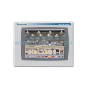
SKU: 2711PC-T10C4D8
Allen-Bradley 2711PC-T10C4D8 Retrofit-Compatible HMI Terminal