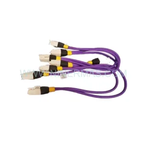
Original Industrial Spare Part
BERGER LAHR FT2000 Service-Ready Spare Part for Industrial Maintenance
Verify the part, confirm the platform family, and move straight into quotation with the right commercial details.
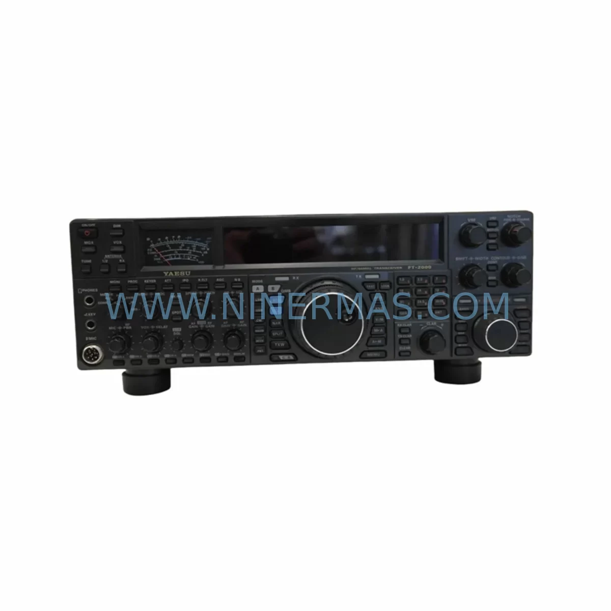
RFQ Ready
- SKUFT2000
- CategoryPLC & Industrial Automation Modules
- BrandBerger Lahr
- SupportAvailability, lead time, condition, and shipping coordination
How Buyers Usually Use This Page
- Confirm the exact part number and platform family before sending the quote request.
- Use direct email when quantity, condition, and destination are already defined internally.
- Switch to the broader brand or category archive when you need alternates nearby.
Series Navigation
Move through the most common platform families behind this part.
Product RFQ
Send this part directly for quotation.
Include quantity, required condition, destination country, and target delivery timing. Current reference: BERGER LAHR FT2000 Service-Ready Spare Part for Industrial Maintenance with SKU FT2000.
BERGER LAHR FT2000 Service-Ready Spare Part for Industrial Maintenance
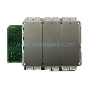
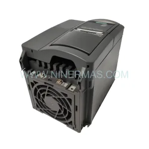
The BERGER LAHR FT2000 is a field-proven stepper motor drive module from the FT Series, widely deployed in discrete manufacturing, packaging lines, textile machinery, and precision positioning systems. As production environments age and OEM support windows close, maintaining a reliable stock of the FT2000 becomes a critical element of any industrial maintenance strategy. NINERMAS supplies the FT2000 as a service-ready spare part — pre-shipment tested, fully inspected, and backed by a 12-month warranty — to support maintenance engineers and procurement teams managing long-lifecycle automation assets.
Unplanned downtime caused by a failed stepper drive can halt an entire production cell within minutes. The FT2000 is a compact, high-reliability drive unit designed for direct integration into existing BERGER LAHR FT Series control architectures. Whether you are executing a scheduled annual overhaul, responding to an emergency fault, or building a strategic spare parts buffer, the FT2000 is a drop-in replacement that restores motion control capability without requiring system redesign or firmware migration.
Our supply chain for the FT2000 is maintained through verified industrial channels, ensuring that each unit delivered meets the original electrical and mechanical specifications. Every module undergoes functional verification prior to dispatch, with test records available upon request. Long-term supply commitments are available for customers managing multi-year maintenance contracts or fleet-wide replacement programs.
Spare Maintenance Table
| Parameter | Specification / Detail |
|---|---|
| Part Number / SKU | FT2000 |
| Brand | BERGER LAHR |
| Series | FT Series |
| Product Type | Stepper Motor Drive Module |
| Application | Discrete manufacturing, packaging, textile, positioning systems |
| Drive Technology | Stepper motor control (open-loop / closed-loop depending on configuration) |
| Mounting | DIN rail / panel mount (FT Series standard) |
| Supply Voltage | Per FT Series specification (verify against system nameplate) |
| Communication Interface | Compatible with FT Series controller bus architecture |
| Operating Temperature | 0°C to +50°C (standard industrial enclosure) |
| Origin | Germany (BERGER LAHR, Schneider Electric Group) |
| Condition | Original spare / tested stock |
| Pre-Shipment Test | Yes — functional verification completed |
| Warranty | 12 months from date of shipment |
| Long-Term Supply | Available — contact for volume and contract pricing |
| Lead Time | Subject to stock availability — confirm at order |
Maintenance Planning for Continuous Operation
When replacing the BERGER LAHR FT2000 in a live production environment, a disciplined maintenance approach requires more than a direct module swap. Maintenance engineers should treat the FT2000 replacement as an opportunity to audit the surrounding electrical circuit and control cabinet for latent faults that may have contributed to the original failure — or that could cause a repeat failure shortly after restoration.
Begin with the 24VDC control power supply feeding the FT Series drive rack. A degraded or undersized power supply is a common root cause of intermittent drive faults and premature module failure. Verify output voltage stability under load and check for ripple or voltage sag during motor acceleration. If the existing power supply is approaching end-of-life, replacing it alongside the FT2000 eliminates a significant risk factor.
Inspect the FT Series backplane or drive bus connector for oxidation, bent pins, or mechanical damage. A compromised backplane connection can cause communication errors between the FT2000 and the host controller, leading to misdiagnosis of the drive as faulty when the actual fault lies in the interconnect. Clean or replace the backplane connector as part of the restoration workflow.
Check all motor phase cables and encoder feedback wiring connected to the FT2000. Insulation breakdown, loose terminal connections, or shielding failures in motor cables are a frequent cause of drive overcurrent trips and IGBT damage. Replace any cable showing signs of heat stress, abrasion, or connector corrosion. Verify that cable shielding is properly grounded at the drive end only, per BERGER LAHR wiring guidelines.
Review the status of associated I/O modules in the same control cabinet. If the FT2000 interfaces with digital I/O cards for enable signals, fault resets, or position triggers, confirm that these modules are functioning correctly and that their 24VDC supply rails are within tolerance. A faulty I/O module sending spurious enable or inhibit signals can cause erratic drive behavior that mimics a drive hardware fault.
For systems using BERGER LAHR WDP or WDPM series programmable controllers as the motion coordinator, verify that the controller firmware and parameter sets are backed up before the replacement. After installing the FT2000, confirm that axis parameters — including current limits, ramp profiles, and step resolution — are correctly loaded and match the original configuration. Parameter loss during a drive swap is a common cause of post-maintenance commissioning delays.
Inspect terminal blocks and DIN rail wiring in the drive section of the cabinet. Loose or corroded terminals on power input, motor output, and signal wiring are a significant reliability risk. Re-torque all terminals to specification and replace any discolored or heat-damaged terminal blocks. Consider installing surge protection devices on the incoming AC supply if the site experiences frequent voltage transients.
If the system includes a safety relay or emergency stop circuit interfacing with the FT2000 enable input, test the full safety chain after replacement. Confirm that the E-stop response time and relay contact integrity meet the original safety specification. Replace any safety relay showing contact wear or delayed dropout.
For facilities managing multiple FT Series axes, it is advisable to maintain a minimum stock of two FT2000 units per production line, alongside a spare FT Series power supply module and a set of pre-terminated motor cables. This buffer inventory strategy reduces mean time to repair (MTTR) from hours to minutes in the event of an unplanned drive failure.
Site Replacement Workflow
Step 1 — Isolation and Lockout: De-energize the control cabinet and apply lockout/tagout (LOTO) per site safety procedures. Confirm that the DC bus of the FT Series drive rack has fully discharged before handling any modules.
Step 2 — Documentation: Photograph the existing wiring, terminal assignments, and module position before removal. Record the drive parameter set if accessible via the host controller or programming tool. This documentation is essential for rapid recommissioning.
Step 3 — Module Removal: Disconnect motor phase cables, encoder feedback, and control signal wiring from the FT2000. Release the module from the backplane connector using the standard FT Series extraction procedure. Inspect the backplane slot for damage before installing the replacement.
Step 4 — Replacement Installation: Insert the new BERGER LAHR FT2000 into the backplane slot and secure all connectors. Reconnect motor cables, encoder wiring, and control signals per the documented terminal assignments. Verify that all cable shields are correctly terminated.
Step 5 — Parameter Restore and Commissioning: Restore the axis parameter set from backup. Power up the system and verify drive status indicators. Execute a low-speed jog test before returning the axis to full production speed. Confirm that all fault codes are cleared and that the motion profile matches the pre-failure baseline.
Step 6 — Documentation Update: Record the replacement in the equipment maintenance log, including the new module serial number, installation date, and test results. Update the spare parts inventory to reflect the consumed unit and initiate a reorder to restore the buffer stock.
Spare Parts Support FAQ
Q1: Is the BERGER LAHR FT2000 a direct drop-in replacement for the existing FT Series installation?
Yes. The FT2000 is designed for direct installation into the BERGER LAHR FT Series drive rack without hardware modification. Confirm the backplane slot assignment and parameter set compatibility before installation. If the host system has been upgraded or the firmware version differs from the original, contact our technical team for compatibility verification prior to ordering.
Q2: What does the 12-month warranty cover, and what is the claims process?
The 12-month warranty covers manufacturing defects and functional failures under normal operating conditions from the date of shipment. It does not cover damage resulting from incorrect installation, overvoltage events, or unauthorized modification. To initiate a warranty claim, contact NINERMAS with the order reference, installation date, and a description of the fault. Replacement or repair will be arranged within the agreed service timeline.
Q3: Can NINERMAS support long-term supply commitments for the FT2000 across a multi-year maintenance contract?
Yes. NINERMAS offers long-term supply programs for industrial spare parts including the BERGER LAHR FT2000. These programs include reserved stock allocation, fixed lead times, and volume pricing for customers managing fleet-wide maintenance or multi-site operations. Contact our procurement team to discuss contract terms and minimum order quantities.
Q4: What pre-shipment testing is performed on the FT2000 before delivery?
Each FT2000 unit undergoes functional verification prior to dispatch, including power-on testing, drive enable/disable response, and output signal integrity checks. Test records are available upon request. Units are packed in anti-static protective packaging with physical inspection documentation included in the shipment. This process ensures that the module arrives in service-ready condition and can be installed directly without additional bench testing.
| Product Series | Other series |
|---|---|
| Country of Origin | US |
Catalog Continuation
More Berger Lahr modules in the catalog.
Use the brand lane to compare nearby part numbers, platform-adjacent modules, and other inquiry-ready listings before sending your final RFQ.
Catalog Continuation
Alternative parts within PLC & Industrial Automation Modules.
Stay inside the same system family when you need substitutes, adjacent modules, or a broader shortlist for procurement review.
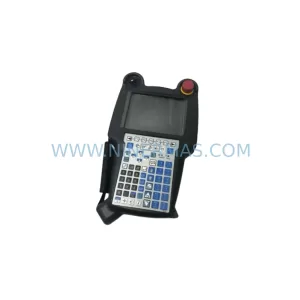
SKU: A05B-2518-C200
FANUC A05B-2518-C200 Retrofit Teach Pendant for Legacy Systems
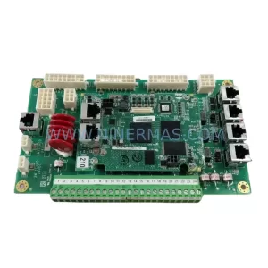
SKU: 2711PC-T10C4D8
Allen-Bradley 2711PC-T10C4D8 Retrofit-Compatible HMI Terminal