Original Industrial Spare Part
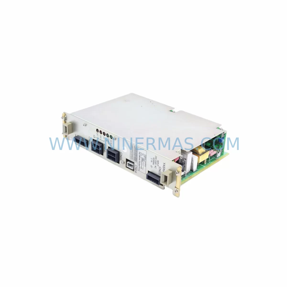
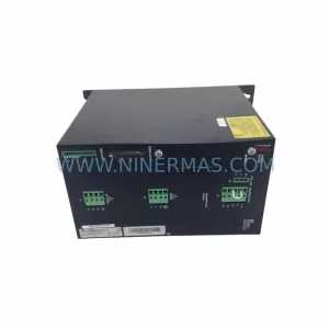
Yaskawa CPS-150F Retrofit-Compatible Power Supply for Legacy Systems
Verify the part, confirm the platform family, and move straight into quotation with the right commercial details.
RFQ Ready
- SKUCPS-150F
- CategoryPLC & Industrial Automation Modules
- BrandYASKAWA
- SupportAvailability, lead time, condition, and shipping coordination
How Buyers Usually Use This Page
- Confirm the exact part number and platform family before sending the quote request.
- Use direct email when quantity, condition, and destination are already defined internally.
- Switch to the broader brand or category archive when you need alternates nearby.
Series Navigation
Move through the most common platform families behind this part.
Product RFQ
Send this part directly for quotation.
Include quantity, required condition, destination country, and target delivery timing. Current reference: Yaskawa CPS-150F Retrofit-Compatible Power Supply for Legacy Systems with SKU CPS-150F.
Yaskawa CPS-150F Retrofit-Compatible Power Supply for Legacy Systems
The Yaskawa CPS-150F is a controller power supply module engineered for the XRC robot controller series, one of Yaskawa Motoman’s most widely deployed industrial robot control platforms. As manufacturing facilities worldwide continue to operate aging XRC-based robot cells, the CPS-150F remains a mission-critical spare part for maintenance engineers, system integrators, and OEMs managing legacy automation lines. Whether you are executing a direct replacement of a failed unit, planning a phased retrofit of an end-of-life control cabinet, or extending the operational lifespan of a production line, the CPS-150F provides a proven, retrofit-compatible power solution that minimises downtime and preserves existing program logic.
NINERMAS maintains ready inventory of the CPS-150F, pre-shipment tested and covered by a 12-month warranty, ensuring your replacement programme is supported from procurement through commissioning.
Upgrade Compatibility Table
| Parameter | CPS-150F Specification | Retrofit Notes |
|---|---|---|
| Compatible Controller | Yaskawa XRC Series | Direct fit for XRC control cabinet backplane |
| Input Voltage | AC 200–230V, 50/60Hz | Verify site supply voltage before installation |
| Output Capacity | 150W rated | Confirm total board load does not exceed rated output |
| Mounting Interface | XRC backplane slot | Check backplane connector alignment with JANCD-MBB02 |
| Terminal Wiring | Screw-type terminal block | Re-use existing wiring harness; verify torque spec |
| Communication Compatibility | N/A (power supply) | No protocol configuration required |
| Replacement Recommendation | Direct drop-in for CPS-150F | No firmware update required |
| Commissioning Focus | Output voltage verification | Measure DC rails before powering servo amplifiers |
| Installation Space | Standard XRC cabinet slot | No mechanical modification required |
| Warranty | 12 Months | Covered from date of shipment by NINERMAS |
Retrofit Planning for Existing Automation Systems
Replacing the CPS-150F within an operational XRC robot cell requires a structured approach that accounts for the interdependencies between the power supply and the surrounding control architecture. Before removing the failed unit, maintenance engineers should document the existing wiring configuration at the terminal block, noting the AC input connections and any auxiliary output feeds supplying ancillary boards within the cabinet.
The XRC controller’s internal architecture distributes DC power from the CPS-150F to several downstream boards. The JANCD-MCP01 CPU board is the primary consumer of the regulated DC supply; any voltage deviation at the power supply output will immediately affect controller boot stability and program execution. Similarly, the JANCD-MSV01 servo control board relies on stable DC rails to maintain axis interpolation accuracy during robot motion. Engineers should verify output voltage levels on all DC rails using a calibrated multimeter before reconnecting downstream boards.
The JANCD-MBB02 backplane board serves as the physical and electrical interconnect between the CPS-150F and all plug-in modules within the XRC cabinet. Inspect the backplane connector for oxidation or mechanical damage before seating the replacement power supply, as connector integrity directly affects power distribution to the JANCD-MIO04 I/O board and any additional I/O expansion modules installed in the rack.
For facilities running XRC controllers with extended I/O configurations, the JANCD-MRY01 relay output board should also be checked for stable supply voltage post-replacement, as relay coil dropout caused by marginal power supply output is a common source of intermittent fault codes during the commissioning phase. If the XRC cell communicates with upstream SCADA or MES systems via DeviceNet or Ethernet, verify that the communication interface boards resume normal operation after the power cycle associated with the CPS-150F swap.
Teach pendant connectivity should be confirmed using the JZRCR-YPP01-1 teach pendant before returning the robot to automatic mode. The pendant’s display and keypad functions are powered through the controller, and a successful pendant handshake confirms that the CPU board has completed its initialisation sequence correctly. If the site uses a programming cable such as the JZRCR-NPP01B-1 for offline program backup or parameter upload, connect and verify communication with the controller before closing the cabinet.
In applications where the XRC controller drives JUSP-ACP25JAA servo amplifiers or similar Yaskawa servo drive units, confirm that the amplifier ready signals are asserted correctly after the power supply replacement. Servo amplifier enable sequences are sensitive to power supply ramp-up timing, and any deviation from the expected DC rail rise time may trigger amplifier fault codes that require manual reset before the robot can resume automatic operation.
Where the retrofit scope extends beyond a single power supply replacement to a broader control cabinet upgrade, consider whether the existing CPS-180F higher-capacity power supply variant is appropriate if additional I/O boards or communication modules have been added to the XRC rack since original installation. Increased board count raises total cabinet power consumption, and operating the CPS-150F at or near its rated capacity over extended periods accelerates component ageing.
Downtime Control During System Migration
Minimising production downtime during a CPS-150F replacement begins with pre-staging the replacement unit and all required tools before the maintenance window opens. NINERMAS ships the CPS-150F with pre-shipment functional testing completed, reducing the risk of receiving a non-functional unit and eliminating the need for incoming inspection delays on the shop floor.
Before initiating the power-down sequence, perform a full backup of the XRC controller’s job files, system parameters, and I/O assignments using the teach pendant or an offline programming tool connected via the JZRCR-NPP01B-1 programming cable. This backup protects against data loss in the event that the controller’s battery-backed memory has been compromised by the power supply failure that necessitated the replacement.
During the physical swap, follow a defined sequence: isolate AC input power at the cabinet breaker, discharge any residual capacitor voltage in the power supply circuit, disconnect the terminal block wiring in documented order, remove the failed CPS-150F from the backplane slot, seat the replacement unit, reconnect wiring in reverse order, and restore AC power. This sequence preserves the integrity of the existing wiring harness and reduces the risk of miswiring errors that could damage downstream boards such as the JANCD-MCP01 or JANCD-MSV01.
After power restoration, allow the XRC controller to complete its full boot sequence before attempting to load programs or enable servo axes. Monitor the controller’s status display and fault log for any error codes that may indicate residual issues with the power supply output or downstream board initialisation. A clean boot with no active faults confirms that the replacement has been completed successfully and that the robot cell is ready to return to production.
For facilities with strict OEE targets, pre-positioning a spare CPS-150F in the local maintenance store as a buffer stock item is strongly recommended. NINERMAS supports long-term inventory agreements for critical spare parts, enabling maintenance teams to maintain on-site stock without committing to large upfront purchases.
Retrofit Support FAQ
Q: Is the CPS-150F a direct replacement for the original Yaskawa unit in the XRC controller?
A: Yes. The CPS-150F supplied by NINERMAS is a direct replacement compatible with the XRC controller backplane. No mechanical modification or firmware update is required. Each unit undergoes pre-shipment functional testing to verify output voltage compliance before dispatch.
Q: What wiring checks should be performed before installing the replacement CPS-150F?
A: Verify AC input voltage at the cabinet terminal block matches the CPS-150F input specification (AC 200–230V). Inspect the terminal block for loose connections, corrosion, or heat damage. Confirm that the backplane connector on the JANCD-MBB02 is clean and undamaged before seating the replacement unit.
Q: How do I confirm the replacement was successful before returning the robot to automatic mode?
A: After power restoration, measure DC output rails with a calibrated multimeter and compare against the rated values. Confirm the JANCD-MCP01 CPU board completes its boot sequence without fault codes. Verify teach pendant communication via the JZRCR-YPP01-1 and confirm servo amplifier ready signals are asserted before enabling automatic operation.
Q: What warranty and stock availability does NINERMAS provide for the CPS-150F?
A: NINERMAS provides a 12-month warranty on the CPS-150F from the date of shipment. We maintain ready inventory for immediate dispatch to support urgent maintenance requirements. Long-term supply agreements are available for facilities requiring guaranteed stock levels for critical spare parts programmes.
| Product Series | Legacy |
|---|---|
| Country of Origin | JP |
Catalog Continuation
More YASKAWA modules in the catalog.
Use the brand lane to compare nearby part numbers, platform-adjacent modules, and other inquiry-ready listings before sending your final RFQ.
SKU: YRC1000 JZRCR-APP01-1
Yaskawa JZRCR-APP01-1 Service-Ready Spare Part for Industrial Maintenance
SKU: YRK01B-1E DX100CPUJZNC-YRK01B-1E JANCD-ASF30-1E 50999-2922R07 CPU50999-2922R07
Yaskawa YRK01B-1E Retrofit-Compatible Servo Board for Legacy Systems
SKU: YPHT31033-1-1 73600-A0101
Yaskawa YPHT31033-1-1 Retrofit-Compatible Gate Driver for Legacy Systems
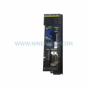
SKU: JAMSC-120CRR11210
Yaskawa JAMSC-120CRR11210 Retrofit-Compatible I/O Module for Legacy Systems
Catalog Continuation
Alternative parts within PLC & Industrial Automation Modules.
Stay inside the same system family when you need substitutes, adjacent modules, or a broader shortlist for procurement review.
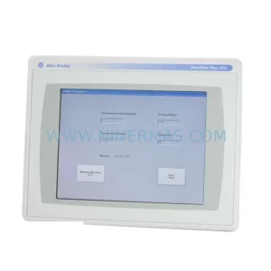
SKU: 2711P-T12C6D2
Allen-Bradley 2711P-T12C6D2 Retrofit-Compatible HMI Display
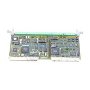
SKU: 6DD1842-0AA0 465842.9000.00
SIEMENS 6DD1842-0AA0 Retrofit-Compatible I/O Module for Legacy Systems
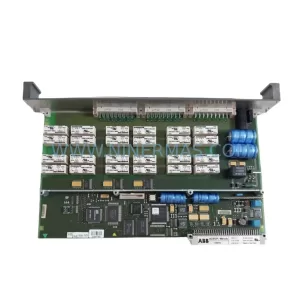
SKU: SCE906A2-002-01 SCE906A200201
Pacific Scientific SCE906A2-002-01 Retrofit Servo Amplifier