Original Industrial Spare Part
Yaskawa YPHT31033-1-1 Retrofit-Compatible Gate Driver for Legacy Systems
Verify the part, confirm the platform family, and move straight into quotation with the right commercial details.
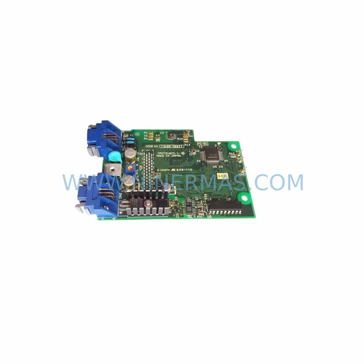
RFQ Ready
- SKUYPHT31033-1-1 73600-A0101
- CategoryPLC & Industrial Automation Modules
- BrandYASKAWA
- SupportAvailability, lead time, condition, and shipping coordination
How Buyers Usually Use This Page
- Confirm the exact part number and platform family before sending the quote request.
- Use direct email when quantity, condition, and destination are already defined internally.
- Switch to the broader brand or category archive when you need alternates nearby.
Series Navigation
Move through the most common platform families behind this part.
Product RFQ
Send this part directly for quotation.
Include quantity, required condition, destination country, and target delivery timing. Current reference: Yaskawa YPHT31033-1-1 Retrofit-Compatible Gate Driver for Legacy Systems with SKU YPHT31033-1-1 73600-A0101.
Yaskawa YPHT31033-1-1 Retrofit-Compatible Gate Driver for Legacy Systems
The Yaskawa YPHT31033-1-1 (part number 73600-A0101) is a gate driver board engineered for medium voltage drive applications within the Yaskawa MV1000 series platform. As industrial facilities face increasing pressure to maintain aging automation infrastructure, this component serves as a critical retrofit solution — enabling plant engineers to restore full drive functionality without committing to a complete system replacement. Whether you are managing a scheduled overhaul or responding to an unplanned drive fault, the YPHT31033-1-1 provides a verified, drop-in compatible path to system recovery with minimal disruption to production continuity.
Yaskawa’s MV1000 series medium voltage drives are widely deployed across power generation, water treatment, mining, cement, and petrochemical industries. Many of these installations have been in service for over a decade, and sourcing original spare parts for end-of-life or discontinued sub-assemblies has become a significant operational challenge. The YPHT31033-1-1 addresses this gap directly — stocked and tested to original Yaskawa specifications, with a 12-month warranty covering both component integrity and functional performance.
Upgrade Compatibility Table
| Parameter | Details |
|---|---|
| Compatible Platform | Yaskawa MV1000 Series Medium Voltage Drive |
| Part Number | YPHT31033-1-1 / 73600-A0101 |
| Component Function | Gate Driver Board — IGBT/GCT firing signal control |
| Backplane Interface | Compatible with MV1000 power cell backplane connectors |
| Communication Compatibility | Supports existing MV1000 internal fiber-optic gate signal links |
| Installation Requirement | Direct board swap; verify torque specs on connector retention screws |
| Replacement Recommendation | Replace as matched pair with companion gate driver where applicable |
| Commissioning Note | Confirm gate signal timing via drive diagnostic menu post-installation |
| Pre-Shipment Testing | Function-tested under simulated load conditions before dispatch |
| Warranty | 12-Month Warranty — covers component defects and functional failure |
Retrofit Planning for Existing Automation Systems
Successful integration of the YPHT31033-1-1 into an existing MV1000 installation requires a structured pre-replacement assessment. Before removing the faulty board, engineers should document the current drive configuration using the CIMR-MV series controller’s parameter backup function — typically executed via the JUSP-NS100 DeviceNet or PROFIBUS communication module, or through a direct RS-232 connection to the programming port. Retaining a full parameter set ensures that motor tuning data, protection thresholds, and ramp profiles are preserved across the board swap.
The YPHT31033-1-1 interfaces directly with the MV1000 power cell assembly. Before installation, inspect the JANCD-MSV01B main control board for any fault codes that may indicate upstream signal issues — a gate driver failure is sometimes symptomatic of a broader fiber-optic link degradation between the control section and the power cell stack. Verify the integrity of the fiber-optic cables connecting the YPHT31033-1-1 to the control board before assuming the gate driver itself is the root cause.
On the power supply side, confirm that the auxiliary 24VDC supply feeding the gate driver circuit is within tolerance. The YPHT31295-1A power supply board, commonly found in the same control cabinet, should be checked for output stability before the new gate driver is energized. An unstable auxiliary supply is a frequent cause of premature gate driver failure and can void warranty coverage if not addressed prior to commissioning.
Terminal wiring on the YPHT31033-1-1 follows the standard MV1000 board connector layout. Cross-reference the wiring diagram against the original installation drawings before reconnecting signal cables. Pay particular attention to the fiber-optic Tx/Rx orientation — reversed connections will prevent gate pulses from reaching the IGBT modules and may trigger a hardware fault on the JANCD-MSV01B. If the installation involves a rack-mounted configuration, confirm that the JZNC-NRK01-1 backplane seating is secure and that all board retention clips are fully engaged before applying power.
For facilities upgrading from an older MV series platform to the MV1000, additional compatibility verification is required. The YPHT31261-1A and YPHT31301-1A gate driver variants used in earlier MV series power cells are not directly interchangeable with the YPHT31033-1-1 without confirming the power cell generation and firmware revision on the JANCD-MSV01B. In mixed-generation installations, the ETC740110-S0050 interface adapter may be required to bridge signal level differences between legacy and current-generation boards.
I/O expansion during the retrofit phase is also an opportunity to address signal isolation requirements. If the existing installation uses direct wiring between the MV1000 control section and field instrumentation, consider adding a signal isolator module to protect the YPHT31033-1-1 from ground loop interference — a common issue in older switchgear rooms where grounding infrastructure has not been updated. The YPHT31097-1A analog I/O board, if present in the same rack, should also be inspected for capacitor aging, as electrolytic capacitor degradation in I/O boards is a leading cause of intermittent faults in drives that have been in service for more than eight years.
HMI screen updates may be required following the board replacement if the drive’s fault history or parameter set has been reset. Coordinate with the site’s control system integrator to verify that the SCADA or DCS interface — whether via Modbus RTU, PROFIBUS DP, or DeviceNet — is re-established and that all analog feedback signals from the drive are correctly scaled in the HMI configuration. This step is frequently overlooked during emergency replacements and can result in process alarms or incorrect speed references being applied to the motor after restart.
Downtime Control During System Migration
Minimizing production downtime during a gate driver replacement on an MV1000 drive requires advance preparation and a disciplined execution sequence. The recommended approach is to pre-stage the YPHT31033-1-1 alongside all required tools, torque specifications, and a printed copy of the relevant wiring diagrams before the maintenance window begins. A cold spare strategy — maintaining at least one YPHT31033-1-1 in the site’s spare parts inventory — reduces mean time to repair (MTTR) from days to hours in the event of an unplanned failure.
Before de-energizing the drive, execute a full parameter backup via the CIMR-MV controller interface and store the file on a dedicated maintenance laptop. This protects the motor tuning data, protection relay settings, and communication node addresses that would otherwise need to be re-entered manually after the board swap. If the drive is part of a redundant configuration, confirm that the standby drive is ready to accept load before initiating the shutdown sequence.
During the physical replacement, follow Yaskawa’s ESD handling procedures for the YPHT31033-1-1 — gate driver boards are sensitive to electrostatic discharge and must be handled with grounded wrist straps and placed on anti-static mats. After installation, perform a visual inspection of all connector seating before applying auxiliary power. The initial power-up sequence should be conducted with the drive in a no-load condition, with gate signal verification performed through the drive’s built-in diagnostic menu before the motor is reconnected.
Post-commissioning, run the drive through a full speed ramp cycle under controlled load conditions and monitor the gate driver temperature via the drive’s thermal protection feedback. Log the commissioning results and update the site’s maintenance records with the replacement date, part number, and any parameter changes made during the process. This documentation supports warranty claims and provides a reference baseline for future predictive maintenance scheduling.
Retrofit Support FAQ
Q1: Is the YPHT31033-1-1 a direct replacement for the original Yaskawa gate driver in the MV1000 series?
Yes. The YPHT31033-1-1 (73600-A0101) is sourced to original Yaskawa specifications and is designed as a direct board-level replacement for the MV1000 series power cell gate driver position. No firmware modification or parameter adjustment is required for a like-for-like swap within the same MV1000 generation. Confirm the power cell generation number before ordering if your installation includes mixed-generation power cells.
Q2: What commissioning steps are required after installing the YPHT31033-1-1?
After physical installation, restore the parameter backup to the CIMR-MV controller, verify fiber-optic Tx/Rx connections, and confirm auxiliary 24VDC supply stability. Power up in no-load mode and use the drive’s diagnostic menu to verify gate pulse timing. Run a controlled load ramp cycle and monitor thermal feedback before returning the drive to full production service. Document all commissioning steps for warranty and maintenance records.
Q3: How do I verify compatibility if my MV1000 installation has been in service for over 10 years?
Provide the full drive nameplate data — including the CIMR-MV model number, power cell serial number, and the part number of the existing gate driver board — when placing your order. Our technical team will cross-reference the part number against the MV1000 generation matrix to confirm compatibility before shipment. For installations with mixed-generation power cells, we will advise on any adapter requirements.
Q4: What does the 12-month warranty cover, and what is the stock availability?
The 12-month warranty covers component defects and functional failure under normal operating conditions. All units are function-tested before dispatch under simulated load conditions. Stock is maintained for immediate shipment; lead times for high-demand periods are communicated at the time of order confirmation. Contact our team at sale@ninermas.com or +0086 187 5021 5667 for real-time stock confirmation and expedited shipping options.
| Product Series | Legacy |
|---|---|
| Country of Origin | JP |
Catalog Continuation
More YASKAWA modules in the catalog.
Use the brand lane to compare nearby part numbers, platform-adjacent modules, and other inquiry-ready listings before sending your final RFQ.
SKU: YRK01B-1E DX100CPUJZNC-YRK01B-1E JANCD-ASF30-1E 50999-2922R07 CPU50999-2922R07
Yaskawa YRK01B-1E Retrofit-Compatible Servo Board for Legacy Systems
SKU: JAMSC-120CRR11210
Yaskawa JAMSC-120CRR11210 Retrofit-Compatible I/O Module for Legacy Systems
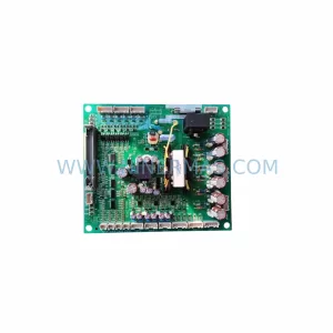
SKU: YPCT31394-1A YPZT31308
YASKAWA YPCT31394-1A YPZT31308 Retrofit-Compatible Control Card for Legacy Systems
Catalog Continuation
Alternative parts within PLC & Industrial Automation Modules.
Stay inside the same system family when you need substitutes, adjacent modules, or a broader shortlist for procurement review.
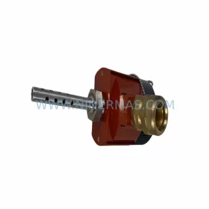
SKU: TRY/PRG/4-20MA/10-30DC
MOORE TRY/PRG/4-20MA/10-30DC Service-Ready Spare Part
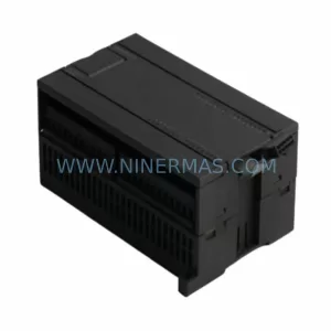
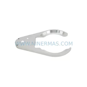
SKU: 5085-404901-11 12INCH 2910-202413-12 404200XRMPD2H14 7-249717
TEL 5085-404901-11 Service-Ready Spare Part for Industrial Maintenance
SKU: DIP011 05-058-011
SIGMATEK DIP011 05-058-011 Service-Ready Spare Part