Original Industrial Spare Part
Mitsubishi AY13 Retrofit-Compatible Digital Output Module
Verify the part, confirm the platform family, and move straight into quotation with the right commercial details.
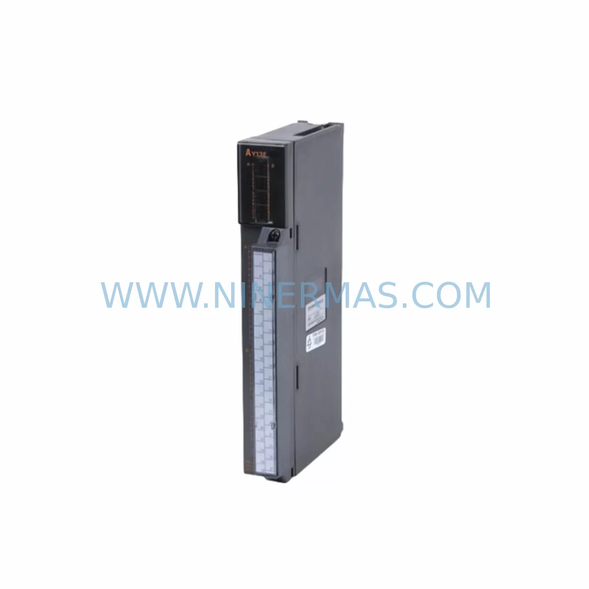
RFQ Ready
- SKUAY13
- CategoryPLC & Industrial Automation Modules
- BrandMitsubishi Electric
- SupportAvailability, lead time, condition, and shipping coordination
How Buyers Usually Use This Page
- Confirm the exact part number and platform family before sending the quote request.
- Use direct email when quantity, condition, and destination are already defined internally.
- Switch to the broader brand or category archive when you need alternates nearby.
Series Navigation
Move through the most common platform families behind this part.
Product RFQ
Send this part directly for quotation.
Include quantity, required condition, destination country, and target delivery timing. Current reference: Mitsubishi AY13 Retrofit-Compatible Digital Output Module with SKU AY13.
Mitsubishi AY13 Retrofit-Compatible Digital Output Module: Legacy System Compatibility & Smooth Upgrade
The Mitsubishi Electric AY13 is a transistor-type digital output module designed for the MELSEC AnS/A series programmable logic controller platform. As production lines age and original equipment manufacturers discontinue support for legacy control hardware, the AY13 has become a critical retrofit component for engineers managing older automation systems across manufacturing, utilities, and process control industries. Whether you are replacing a failed output module in an existing control cabinet, expanding I/O capacity on a legacy rack, or migrating a complete control system to a modern platform, the AY13 provides a reliable, drop-in-compatible solution that minimizes engineering rework and reduces unplanned downtime.
The AY13 delivers 16 points of transistor sink-type digital output, operating at 12–24 VDC with a rated load current of 0.1 A per point. Its compact form factor is designed to fit directly into AnS-series base units such as the A1S32B and A1S65B racks, making it fully compatible with existing backplane wiring and slot addressing schemes. For engineers working on retrofit projects, this means the module can be installed without modifying the base unit, rewiring terminal blocks, or reprogramming module addresses in the CPU — a significant advantage when downtime windows are measured in hours rather than days.
Upgrade Compatibility Table
| Parameter | Details |
|---|---|
| Compatible Series | MELSEC AnS / A Series (A1S, A2S, A0J2H) |
| Output Points | 16 points (transistor sink type) |
| Rated Output Voltage | 12–24 VDC |
| Rated Load Current | 0.1 A per point / 1.6 A per common |
| Compatible Base Units | A1S32B, A1S65B, A1S68B (AnS-series racks) |
| Terminal Block | 40-pin connector (compatible with existing field wiring) |
| Communication Compatibility | Backplane bus — no protocol configuration required |
| Replacement Recommendation | Direct replacement for AY13, AY13E; cross-reference AY22, AY23 for higher current applications |
| Commissioning Notes | Verify slot address in GX Developer / GX Works2; confirm I/O assignment in PLC program |
| Warranty | 12 months from date of shipment |
Retrofit Planning for Existing Automation Systems
Successful integration of the AY13 into an existing control system requires a structured approach to hardware verification, wiring confirmation, and software validation. Before ordering, engineers should confirm the target base unit model — the A1S32B supports up to 32 I/O points per slot group, while the A1S65B and A1S68B accommodate larger configurations. Slot numbering must be verified against the existing PLC program to ensure the replacement module occupies the same logical address as the original unit.
Field wiring connected to the original AY13 terminal block should be documented before removal. The 40-pin connector layout is standardized across the AnS output module family, so existing wiring harnesses typically connect without modification. However, engineers should verify load voltage and current ratings for each output channel, particularly in applications where actuators, solenoid valves, or relay coils have been added or replaced since the original system commissioning.
In systems where the A1SCPU or A2SCPU serves as the main controller, the AY13 communicates via the backplane bus without requiring any network configuration. This is a key advantage over systems that use remote I/O modules connected via CC-Link or MELSECNET/H, where network parameter settings and station addresses must be carefully preserved during module replacement. If the retrofit project involves migrating from an AnS-series CPU to a newer Q-series or iQ-R series controller — for example, replacing an A1SCPU with a Q02UCPU — the I/O module lineup will need to be updated to QY10 or QY18A output modules, and the control program will require conversion using GX Works2 or GX Works3 migration tools.
Power supply capacity is a critical verification step in any retrofit project. The A1S61P or A1S62P power supply modules installed in the base unit must provide sufficient capacity to support all installed I/O modules, including the replacement AY13. Engineers should calculate the total current draw across all occupied slots and confirm that the power supply’s rated output — typically 5 VDC internal bus — is not exceeded. If the existing power supply is operating near its rated capacity, a replacement or supplementary A1S63P unit may be required.
For systems that include analog I/O modules such as the A1S68AD or A1S62DA alongside digital output modules, the slot configuration and I/O map must be reviewed holistically. Adding or replacing a digital output module can shift the I/O address assignments of adjacent modules if the PLC program uses absolute addressing rather than symbolic tags. This is particularly relevant in older GX Developer projects where I/O device assignments are hardcoded rather than defined through a structured tag database.
Communication modules installed in the same rack — such as the A1SJ71QBR11 for CC-Link master functionality or the A1SJ71UC24-R4 for RS-232C/RS-422 serial communication — are not affected by the replacement of a digital output module, provided the slot configuration remains unchanged. However, if the retrofit involves reorganizing the module layout within the rack, communication module station addresses and network parameters must be re-verified in GX Developer before restarting the system.
HMI screens connected to the control system via RS-232C, RS-422, or Ethernet — including GOT1000 series panels such as the GT1575-VNBA — reference device addresses that correspond to the PLC’s I/O map. If the AY13 replacement results in any change to output coil addresses (Y-device assignments), the HMI project must be updated accordingly to maintain correct display and control functionality. In most direct replacement scenarios, no HMI changes are required.
Downtime Control During System Migration
Minimizing production downtime during a module replacement or system migration is a primary concern for maintenance engineers and plant managers. The AY13’s direct compatibility with the AnS-series backplane means that a straightforward module swap — without rack reconfiguration or program modification — can typically be completed within a planned maintenance window of two to four hours, including pre-shutdown verification, physical replacement, power-up testing, and output channel confirmation.
Before initiating the replacement, engineers should back up the existing PLC program using GX Developer or GX Works2, saving the project file to a secure location. The current I/O forced output status and any active latched coils should be documented to ensure the system returns to its correct operating state after restart. If the system includes a battery-backed A1SMCA memory cassette, the program backup is preserved automatically, but a manual backup is still recommended as a precaution.
During the physical replacement, the base unit power supply should be switched off and the 40-pin terminal block connector disconnected before removing the AY13 module from its slot. The replacement module should be inserted firmly until the front connector is fully seated, and the terminal block reconnected with all field wiring verified against the original documentation. After power-up, the CPU’s RUN/STOP switch should remain in STOP mode during initial output verification to prevent unintended actuator activation.
Output channel testing should be performed using the GX Developer monitor function or the GOT panel’s I/O monitor screen to force each output point individually and confirm correct field device response. Once all 16 output channels have been verified, the CPU can be returned to RUN mode and normal production resumed. This structured commissioning approach protects the original program logic, maintains field control continuity, and reduces the risk of post-replacement faults that could extend the downtime window.
Retrofit Support FAQ
Q: Is the AY13 a direct replacement for the original Mitsubishi AY13 installed in my AnS-series rack?
A: Yes. The AY13 is a direct slot-compatible replacement for the original module. It uses the same 40-pin terminal block connector, occupies the same backplane slot, and requires no changes to the PLC program or I/O address assignments in standard replacement scenarios. Verify the base unit model and slot address before installation.
Q: What commissioning steps are required after installing the replacement AY13?
A: After installation, power up the system with the CPU in STOP mode. Use GX Developer or GX Works2 to verify that the module is recognized in the I/O configuration. Force each output channel individually using the monitor function and confirm correct field device response. Return the CPU to RUN mode only after all output channels have been verified.
Q: Can the AY13 be used in a system that is being migrated from AnS-series to Q-series hardware?
A: The AY13 is designed for AnS-series base units and is not directly compatible with Q-series racks. For Q-series migrations, the equivalent output modules are the QY10 (transistor sink, 16 points) or QY18A (transistor sink, 16 points, high-density). Program conversion from AnS to Q-series requires GX Works2 and careful review of I/O device assignments.
Q: What warranty and supply terms apply to this module?
A: All AY13 modules supplied by NINERMAS COMPANY LIMITED carry a 12-month warranty from the date of shipment, covering manufacturing defects and functional failures under normal operating conditions. Pre-shipment functional testing is performed on all units. Stock availability is maintained for prompt dispatch. Contact sale@ninermas.com or +0086 187 5021 5667 for current inventory status and lead times.
| Product Series | MELSEC |
|---|---|
| Country of Origin | JP |
Catalog Continuation
More Mitsubishi Electric modules in the catalog.
Use the brand lane to compare nearby part numbers, platform-adjacent modules, and other inquiry-ready listings before sending your final RFQ.
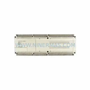
SKU: A50CA55C BC186A433G53
Mitsubishi A50CA55C BC186A433G53 Spare Part for Maintenance
SKU: MELSEC RD77MS16 D 0140-76929 GAS N2, 40 SLM UFC-1660
Mitsubishi RD77MS16 Safety-Reliable Motion for Critical Sites
Catalog Continuation
Alternative parts within PLC & Industrial Automation Modules.
Stay inside the same system family when you need substitutes, adjacent modules, or a broader shortlist for procurement review.
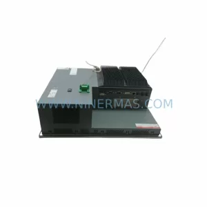
SKU: PFXPP170CA66K00N00
Pro-face PFXPP170CA66K00N00 Service-Ready Spare Part

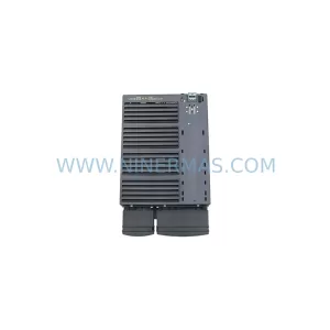
SKU: 6SL3224-0BE32-2UA0
Siemens 6SL3224-0BE32-2UA0 Retrofit PM240 Power Module