Original Industrial Spare Part
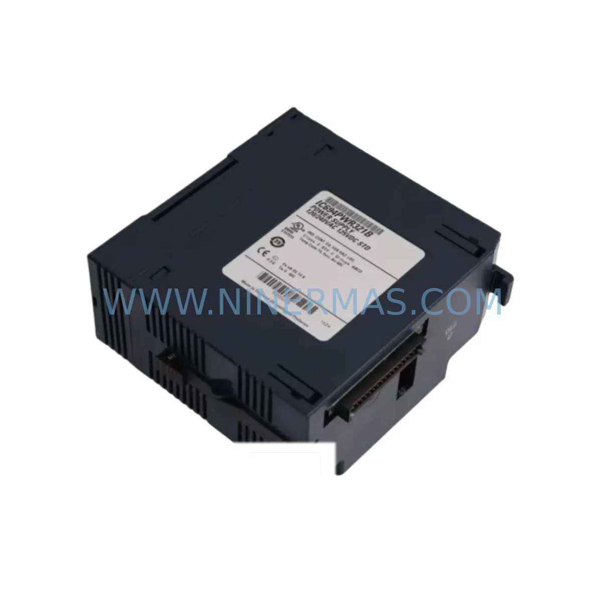
GE IC694PWR321B Retrofit-Compatible Power Supply for Legacy Systems
Verify the part, confirm the platform family, and move straight into quotation with the right commercial details.
RFQ Ready
- SKUIC694PWR321B
- CategoryPLC & Industrial Automation Modules
- BrandGE
- SupportAvailability, lead time, condition, and shipping coordination
How Buyers Usually Use This Page
- Confirm the exact part number and platform family before sending the quote request.
- Use direct email when quantity, condition, and destination are already defined internally.
- Switch to the broader brand or category archive when you need alternates nearby.
Series Navigation
Move through the most common platform families behind this part.
Product RFQ
Send this part directly for quotation.
Include quantity, required condition, destination country, and target delivery timing. Current reference: GE IC694PWR321B Retrofit-Compatible Power Supply for Legacy Systems with SKU IC694PWR321B.
GE IC694PWR321B Retrofit-Compatible Power Supply for Legacy Systems
The GE IC694PWR321B is a 120/240 VAC input power supply module designed for the GE Series 90-30 programmable logic controller platform. As legacy Series 90-30 systems approach end-of-life and original spare parts become increasingly scarce, the IC694PWR321B remains one of the most sought-after retrofit-compatible components for plant engineers tasked with sustaining aging control infrastructure. Whether you are replacing a failed unit in a running production line, upgrading a control cabinet to extend its operational lifespan, or migrating from an obsolete power architecture, the IC694PWR321B provides a reliable, drop-in compatible solution that minimises engineering rework and reduces unplanned downtime.
The IC694PWR321B delivers regulated DC power to the Series 90-30 CPU rack and expansion racks, supporting a broad range of I/O modules, communication modules, and specialty modules that populate the backplane. Its compatibility with the standard 5-slot, 10-slot, and expansion rack configurations makes it a versatile choice for both compact control panels and larger distributed control architectures. Engineers replacing a failed IC694PWR321 (non-B revision) or an IC694PWR330 high-capacity unit should carefully verify the total rack power budget before substitution, as the 321B variant is rated for a specific output current that may differ from adjacent model numbers in the Series 90-30 power supply family.
When planning a retrofit around the IC694PWR321B, the first step is a thorough power capacity audit. Sum the current draw of every module installed in the rack — including the IC694CPU364 or IC694CPU374 central processing unit, any IC694MDL series discrete I/O modules, IC694ALG analog input and output modules, IC694CMM321 or IC694CMM302 communications modules, and any third-party specialty cards — and confirm that the aggregate load falls within the IC694PWR321B’s rated output. Overlooking a high-draw analog output module or a communications coprocessor is a common source of nuisance trips after a power supply swap.
Upgrade Compatibility Table
| Parameter | IC694PWR321B Details |
|---|---|
| Input Voltage | 120/240 VAC, 47–63 Hz (auto-ranging) |
| Output Voltage | +5 VDC, +24 VDC (backplane) |
| Rack Compatibility | GE Series 90-30: IC693CHS391, IC694CHS392, IC694CHS398 (5- and 10-slot) |
| Backplane Interface | Direct backplane connector — no external wiring to CPU or I/O modules |
| Terminal Block Wiring | L1, L2/N, Ground — standard 3-wire AC input; verify torque spec (0.5–0.6 Nm) |
| Communication Compatibility | Compatible with Ethernet (IC694CMM321), Serial (IC694CMM302), and Genius Bus modules on same rack |
| Direct Replacement For | IC694PWR321 (earlier revision), IC693PWR321 (Series 90-30 legacy) |
| Installation Space | Occupies Power Supply slot (leftmost position) — no additional DIN rail space required |
| Commissioning Note | Cycle rack power after installation; verify CPU status LEDs and I/O module OK indicators before resuming production |
| Warranty | 12 Months — covers manufacturing defects; includes pre-shipment functional test |
Retrofit Planning for Existing Automation Systems
A successful IC694PWR321B retrofit begins well before the module arrives on site. Start by pulling the rack configuration printout from your GE Proficy Machine Edition or Logicmaster 90-30 programming software to document every occupied slot and its associated module part number. This record becomes your baseline for verifying that the replacement power supply can sustain the existing load without modification to the I/O complement.
Terminal block wiring is straightforward but must be executed carefully. The IC694PWR321B uses a removable screw-terminal connector for AC input. Before disconnecting the old unit, photograph or sketch the existing wiring — L1, L2/N, and protective earth — and confirm that the incoming supply voltage matches the module’s auto-ranging input specification. If the control cabinet feeds 240 VAC from a transformer secondary, verify that the neutral conductor is correctly identified and that the earth bond meets local electrical code requirements.
Backplane seating is the next critical step. The IC694PWR321B slides into the leftmost slot of the Series 90-30 rack and locks via the standard module latch. Inspect the backplane connector pins for corrosion or mechanical damage before insertion — a degraded backplane on an aging IC694CHS392 or IC694CHS398 rack can cause intermittent power faults that are difficult to distinguish from a faulty power supply. If the rack itself is suspect, consider sourcing a replacement chassis as part of the same retrofit project.
Once the module is seated and AC power is restored, observe the PWR LED on the IC694PWR321B and the OK LEDs on each I/O module. A solid green PWR LED with all module OK LEDs illuminated confirms that the backplane power rails are within specification. If any module fails to initialise, check the slot address configuration in your PLC program — the IC694CPU364 or IC694CPU374 CPU will fault on an unexpected module type or a missing module at a configured address. Use Proficy Machine Edition or Logicmaster 90-30 to go online, verify the hardware configuration, and clear any I/O faults before returning the system to automatic mode.
For systems that include an IC694CMM321 Ethernet communications module or an IC694CMM302 serial communications module, confirm that the network link is re-established after the power cycle. SCADA systems, HMI panels, and historian servers that poll the PLC via Ethernet/IP or SRTP may require a brief reconnection delay — build this into your maintenance window planning. Similarly, if the rack hosts a Genius Bus Controller communicating with remote I/O drops, verify that all Genius blocks report healthy status on the bus after power restoration.
Installations that include analog signal conditioning should also verify IC694ALG analog input and output modules after the power supply swap. Analog modules are sensitive to supply rail stability, and a marginal backplane connection can introduce offset errors or noise that affect process control loops. A brief calibration check or a comparison against a known-good reference signal is good practice before signing off on the retrofit.
Downtime Control During System Migration
Minimising production downtime during a Series 90-30 power supply replacement requires disciplined pre-work. The most effective strategy is to prepare the replacement IC694PWR321B in advance — bench-test it if possible, confirm firmware revision compatibility with your CPU, and have all tools, torque specifications, and wiring documentation ready before the maintenance window opens.
Where process continuity is critical, consider whether a hot-standby or redundant CPU configuration is in place. Series 90-30 systems with a redundant CPU pair (using IC694CPU374 units and a redundancy link module) can transfer control to the standby CPU while the primary rack’s power supply is replaced, dramatically reducing the impact on the controlled process. If redundancy is not available, coordinate with operations to bring the process to a safe hold state, lock out and tag out the control panel, and execute the swap during a planned production break.
Protect the existing PLC program before any hardware work begins. Use Proficy Machine Edition or Logicmaster 90-30 to upload and save the current program, including all data blocks, configuration files, and motion parameters, to a secure engineering workstation. This backup is your recovery point if the CPU loses its program during the power interruption — a rare but possible event on older CPUs with degraded battery-backed RAM. Replacing the CPU battery (IC693ACC302 or equivalent) as part of the same maintenance visit is a low-cost precaution that eliminates this risk.
After the IC694PWR321B is installed and the system is powered up, perform a structured commissioning check: verify CPU RUN mode, confirm all I/O modules are faulted-clear, check communications links, and run a short functional test of critical outputs before releasing the system to automatic control. Document the replacement in your maintenance management system, including the new module’s serial number and the date of installation, to support future warranty claims and spare parts lifecycle planning.
Retrofit Support FAQ
Q1: Is the IC694PWR321B a direct drop-in replacement for the IC694PWR321 and IC693PWR321?
Yes. The IC694PWR321B is the current revision of the Series 90-30 standard power supply and is mechanically and electrically compatible with the IC694PWR321 (earlier revision) and the IC693PWR321 used in older Series 90-30 racks. No wiring changes or rack modifications are required. Confirm the total rack load is within the rated output before installation.
Q2: What commissioning steps are required after installing the IC694PWR321B?
After seating the module and restoring AC power, verify the PWR LED status, confirm all I/O module OK LEDs are illuminated, go online with Proficy Machine Edition or Logicmaster 90-30 to clear any hardware faults, and re-establish all communications links (Ethernet, serial, Genius Bus) before returning the system to automatic mode. A functional output test is recommended before releasing to production.
Q3: Does the IC694PWR321B ship with a pre-shipment functional test?
Yes. Every IC694PWR321B unit supplied by NINERMAS undergoes a pre-shipment functional test to verify output voltage regulation and module health. Units are shipped with a 12-month warranty covering manufacturing defects. Test records are available on request.
Q4: What is the lead time and stock availability for the IC694PWR321B?
NINERMAS maintains inventory of the IC694PWR321B to support urgent retrofit and breakdown replacement requirements. In-stock units are typically dispatched within 1–2 business days. For large-quantity orders or long-term supply agreements to support multi-site maintenance programmes, contact our sales team to discuss dedicated stock allocation and extended supply commitments.
| Product Series | 90-30 |
|---|---|
| Country of Origin | US |
Catalog Continuation
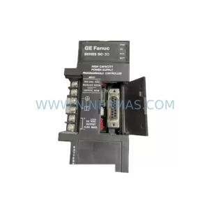
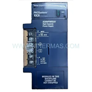
Nearby part numbers around IC694PWR.
Use this lane when the buyer is comparing adjacent model numbers, revision-near items, or closely related spare variants within the same brand family.
Catalog Continuation
More GE modules in the catalog.
Use the brand lane to compare nearby part numbers, platform-adjacent modules, and other inquiry-ready listings before sending your final RFQ.
Catalog Continuation
Alternative parts within PLC & Industrial Automation Modules.
Stay inside the same system family when you need substitutes, adjacent modules, or a broader shortlist for procurement review.
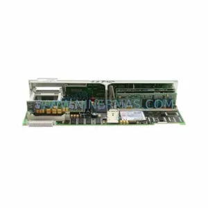
SKU: 6FC5357-0BB12-0AE0
Siemens 6FC5357-0BB12-0AE0 Service-Ready Industrial Spare Part
SKU: 3BSE011790R1(PXHK401)
ABB 3BSE011790R1 PXHK401 Retrofit-Ready Communication Module
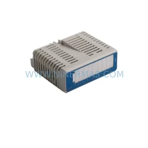
SKU: DI890 3BSC690073R1
ABB DI890 3BSC690073R1 Retrofit-Compatible Digital Input for Legacy S800