Description
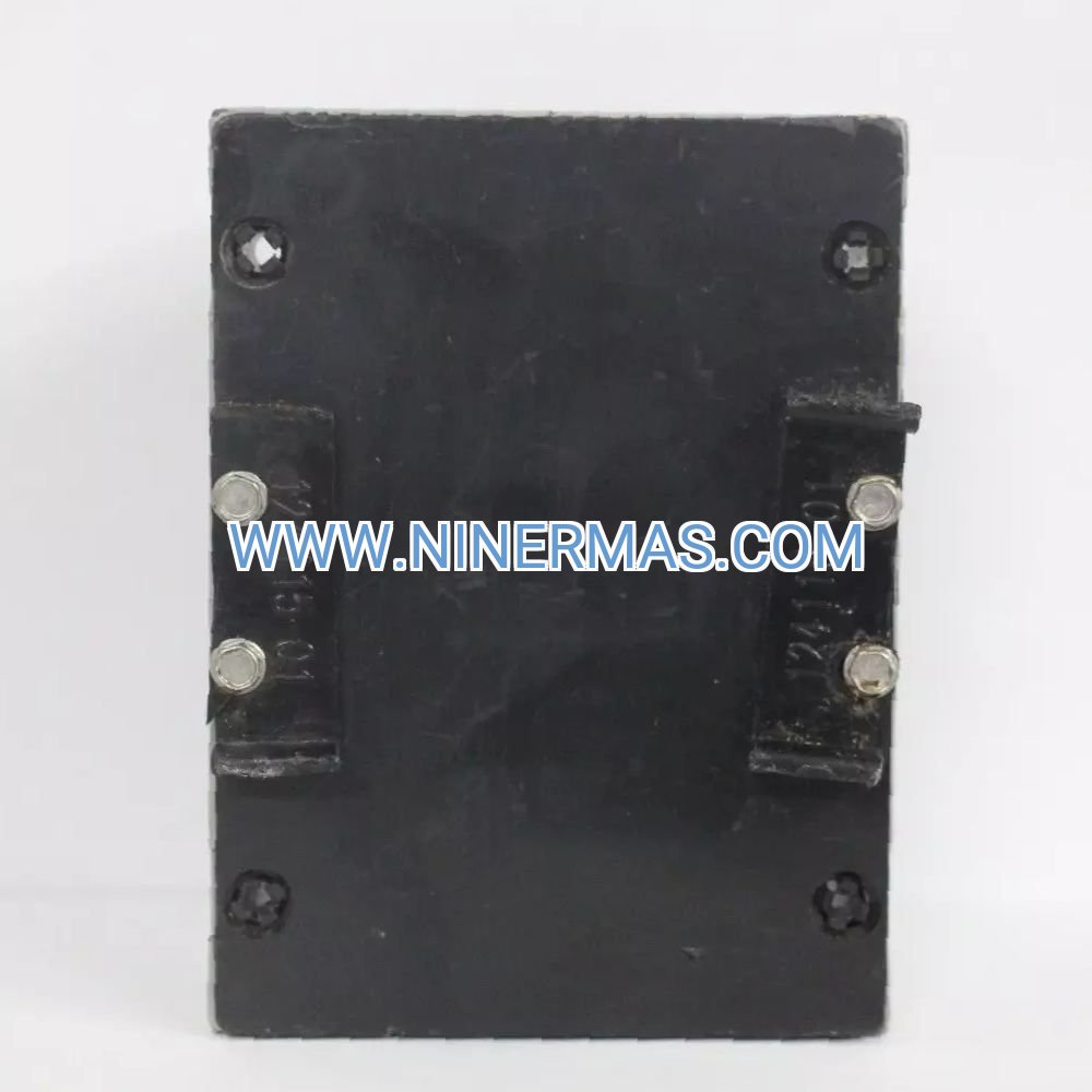
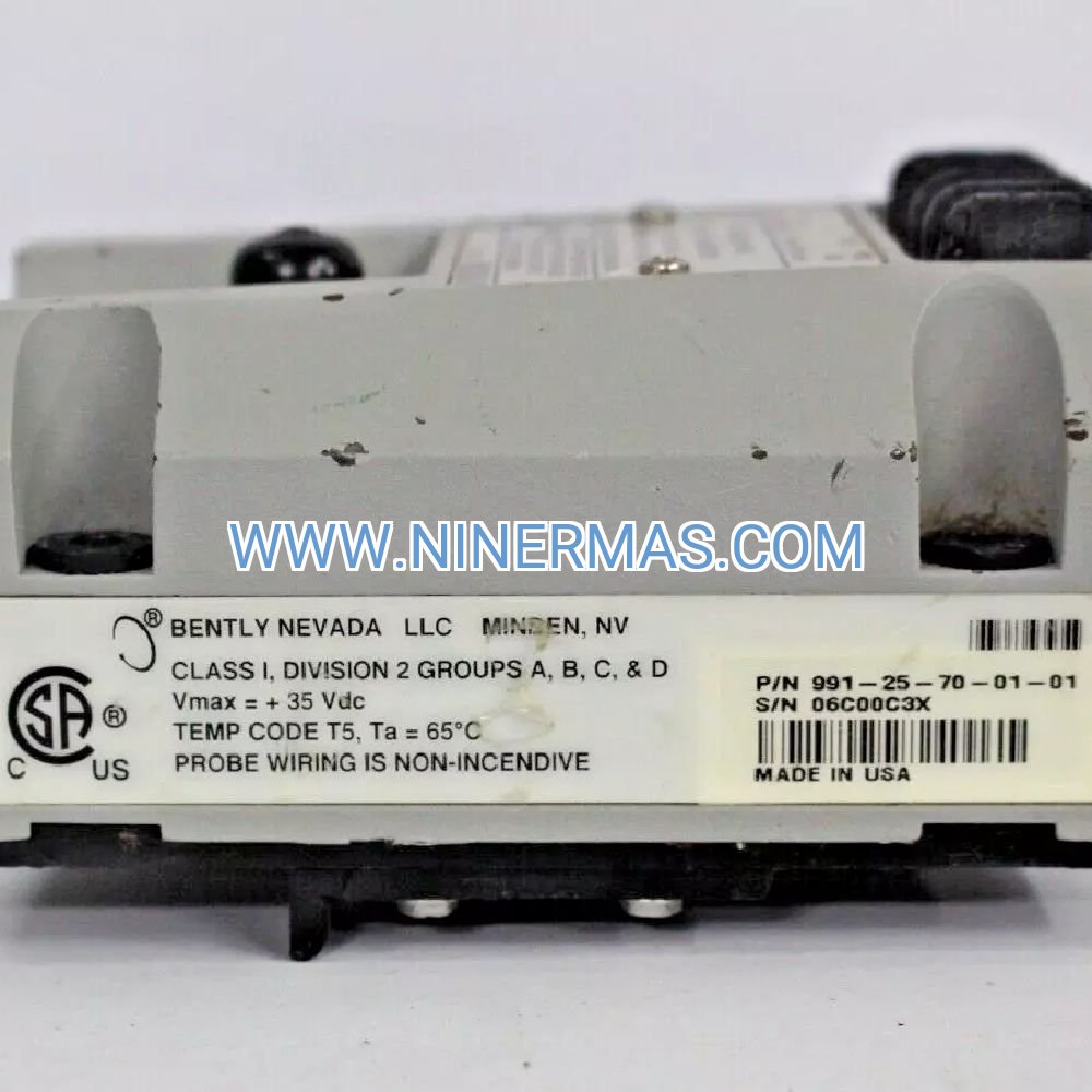
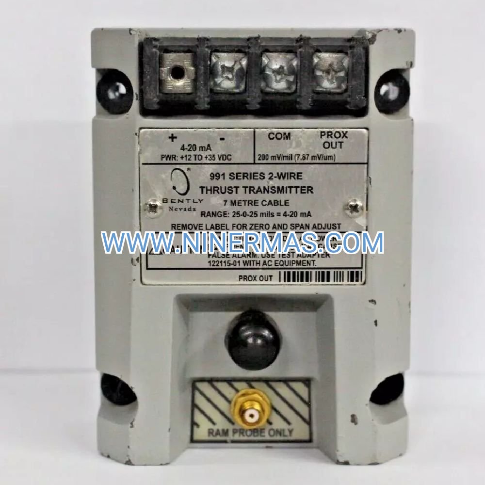
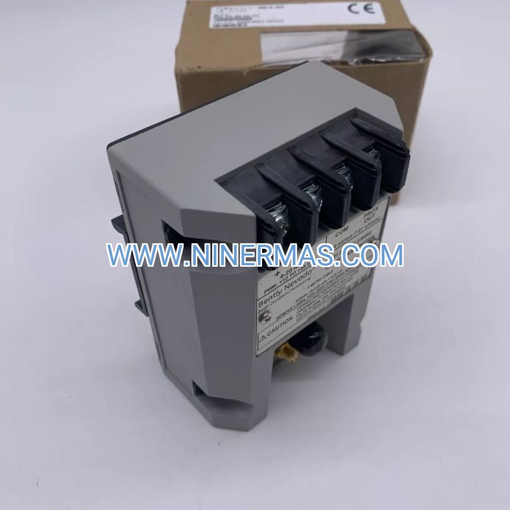
991-25-70-01-01 Thrust Position Transmitter (Industrial-Grade Axial Monitoring)
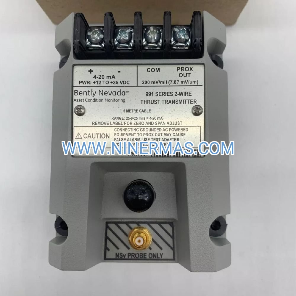
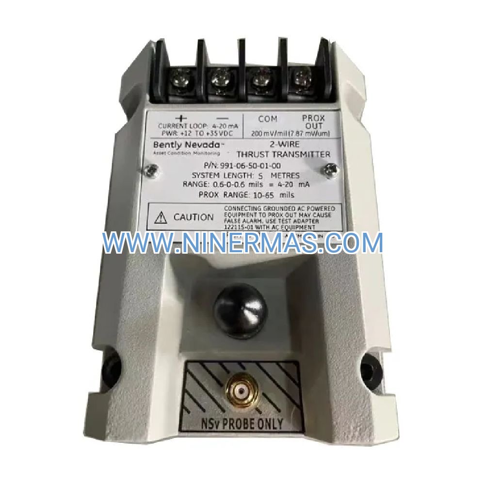
The 991-25-70-01-01 is an industrial-grade thrust position transmitter that converts proximity probe signals into standardized 4-20 mA current outputs for real-time axial rotor monitoring. Designed for critical turbomachinery applications, this device safeguards against thrust bearing failures by providing continuous surveillance of rotor axial displacement with ±1% full-scale accuracy.
Engineered for steam turbines, gas compressors, and high-speed rotating equipment, the 991-25-70-01-01 integrates seamlessly with DCS, PLC, and SCADA systems through its loop-powered 4-20 mA interface. The transmitter processes dual proximity probe inputs to calculate differential axial position, eliminating thermal expansion errors while delivering reliable early-warning detection of bearing degradation.
With explosion-proof NEMA 4X/IP66 housing and conformal-coated electronics, this thrust monitor operates reliably in temperatures from -30°C to +65°C. Field-adjustable zero and span calibration enable precise alignment to specific thrust bearing clearances, while built-in fault detection drives output to diagnostic levels upon probe or cable failures.
Key Performance Features
✓ Precision Differential Measurement
Dual-probe configuration calculates net axial displacement by subtracting opposing probe gap voltages, automatically compensating for thermal growth and shaft runout to deliver true thrust position data with <100ms response time.
✓ Universal Control System Integration
Standard 2-wire 4-20 mA current loop output connects directly to any DCS analog input card, PLC module, or SCADA RTU without signal conditioning hardware, supporting loads up to 750Ω at 24 VDC supply voltage.
✓ Intelligent Fault Diagnostics
Automatic probe failure detection drives output to 3.8 mA or 20.5 mA upon loss of signal, enabling immediate differentiation between mechanical thrust excursions and sensor system faults for faster troubleshooting and reduced downtime.
✓ Harsh Environment Durability
Explosion-proof aluminum enclosure with IP66 ingress protection and conformal-coated circuitry resists moisture, salt spray, chemical vapors, and temperature extremes, delivering MTBF >100,000 hours in demanding industrial installations.
✓ Field-Calibratable Accuracy
Adjustable zero and span potentiometers allow on-site calibration to match specific thrust collar dimensions and bearing clearances, maintaining ±1% accuracy across the full 0.6 mm measurement range without factory recalibration.
✓ Loop-Powered Simplicity
Two-wire design draws operating power directly from the 4-20 mA receiver circuit, eliminating separate power supply requirements and reducing installation complexity in multi-channel monitoring systems.
Industrial Application Solutions
→ Power Generation Turbines
Challenge: Steam turbine thrust bearing failures cause catastrophic rotor-to-stator contact within seconds, resulting in million-dollar damage and extended outages.
Solution: Continuous 4-20 mA thrust position monitoring enables automated turbine trip at ±0.5 mm deviation, preventing contact damage while trending data reveals gradual bearing wear for predictive maintenance scheduling.
→ Process Gas Compressors
Challenge: Centrifugal compressor axial instability indicates impeller fouling, aerodynamic imbalance, or seal degradation, but traditional vibration monitoring cannot isolate thrust-specific issues.
Solution: Differential thrust measurement distinguishes axial movement from radial vibration, correlating position shifts with process upsets to identify root causes and optimize cleaning intervals.
→ Cryogenic Turboexpanders
Challenge: Hydrocarbon and LNG expanders operate at -160°C with micron-level axial clearances where thermal transients during startup cause temporary thrust excursions that must not trigger false trips.
Solution: Fast <100ms response time captures transient events while adjustable alarm setpoints accommodate normal startup behavior, balancing equipment protection with operational availability.
→ Offshore Platform Machinery
Challenge: Unmanned offshore compressors and generators require remote thrust monitoring with intrinsically safe installations in hazardous classified areas.
Solution: Explosion-proof housing meets Class I Division 1 requirements while 4-20 mA output transmits over long cable runs to onshore SCADA systems without signal degradation or repeater amplifiers.
→ Hydro Turbine Generators
Challenge: Water turbines experience hydraulic thrust variations during load changes and wicket gate adjustments that can exceed bearing design limits if not continuously monitored.
Solution: Real-time axial position trending correlates thrust changes with gate position and head pressure, enabling operators to optimize loading sequences and avoid bearing overload conditions.
Technical Specifications & Selection Guide
| Parameter | Specification | Notes |
|---|---|---|
| Model Number | 991-25-70-01-01 | Factory configuration code |
| Measurement Range | 0.6 mm (25 mils) full scale | Axial displacement, bidirectional |
| Output Signal | 4-20 mA DC | 2-wire loop-powered |
| Accuracy | ±1% of full scale | Over operating temperature range |
| Response Time | <100 ms to 90% | Suitable for transient capture |
| Power Supply | 12-30 VDC | From 4-20 mA receiver |
| Load Resistance | Max 750 Ω @ 24 VDC | Calculate voltage drop for long cables |
| Operating Temp | -30°C to +65°C | -22°F to +149°F |
| Enclosure Rating | NEMA 4X / IP66 | Explosion-proof aluminum |
| Probe Compatibility | 3300 XL 8mm proximity probes | Dual opposing configuration |
| System Length | 5 m or 7 m options | Probe + extension cable total |
| MTBF | >100,000 hours | Normal operating conditions |
Selection Criteria:
- Choose 991-25-70-01-01 for standard 0.6 mm thrust bearing clearances in turbines and compressors rated below 50 MW
- Select 5-meter system length for compact machinery with transmitter mounted within 3 meters of thrust collar
- Specify 7-meter system length for large turbines requiring remote transmitter mounting or routing through cable trays
- Verify DCS/PLC analog input accepts 4-20 mA and provides 24 VDC loop power with sufficient current capacity (typical 25 mA)
- For ranges exceeding 0.6 mm, consider 991-50-XX-01-00 model with 1.27 mm (50 mil) full scale capability
Advanced Integration Capabilities
Machinery Protection System Hardwiring
Connect 4-20 mA output to dedicated trip amplifier modules in Bently Nevada 3500 racks or equivalent protection systems. Configure dual setpoint logic: Alert at ±0.3 mm (10 mA or 14 mA) for operator notification, Danger at ±0.5 mm (8 mA or 16 mA) for automatic turbine shutdown via emergency trip solenoid.
Parallel Monitoring Architecture
Split 4-20 mA signal using loop-powered isolators to feed both DCS trending inputs and independent safety PLC shutdown logic, ensuring continued protection even during DCS maintenance or communication failures.
Wireless Gateway Integration
Interface 4-20 mA output to WirelessHART or ISA100 transmitters for retrofit installations where hardwired cabling is cost-prohibitive, enabling remote monitoring of previously unmonitored equipment.
Predictive Analytics Platforms
Stream high-resolution thrust position data to cloud-based condition monitoring services via edge computing gateways, applying machine learning algorithms to detect subtle degradation patterns weeks before traditional alarm thresholds are exceeded.
Delivery Timeline & Service Commitment
Standard Lead Time: 3-5 business days for in-stock units; expedited same-day shipping available for critical outage support at additional cost.
Custom Configurations: 2-3 weeks for non-standard system lengths or special calibration ranges requiring factory programming.
Warranty Coverage: 24-month manufacturer's warranty covering defects in materials and workmanship; extended 60-month coverage available for critical sparing applications.
Technical Support: Unlimited phone and email consultation with application engineers experienced in turbomachinery protection system design and troubleshooting.
Documentation Package: Each unit ships with calibration certificate, installation manual, wiring diagrams, and dimensional drawings in PDF format.
Calibration Services: Annual recalibration available at factory or authorized service centers with NIST-traceable standards and updated certification.
Frequently Asked Questions
Q: How does the 991-25-70-01-01 interface with existing Bently Nevada 3500 monitoring systems?
A: The 4-20 mA output connects directly to 3500/45 Position Monitor analog input channels or 3500/92 Communication Gateway for System 1 integration. Alternatively, use the transmitter to feed standalone DCS inputs while retaining 3500 rack for vibration monitoring, creating redundant thrust surveillance.
Q: What is the maximum cable distance between transmitter and DCS input card?
A: With 24 VDC supply and 750Ω load limit, maximum distance is approximately 1500 meters using 18 AWG twisted-pair cable (25Ω/km resistance). For longer runs, use 16 AWG cable or increase supply voltage to 28 VDC to compensate for voltage drop.
Q: Can the transmitter measure absolute thrust position or only relative changes?
A: The device measures relative axial displacement from the calibrated zero point. To establish absolute position reference, perform initial zero calibration with rotor at magnetic center (equal probe gaps), then track deviations as positive or negative travel from that datum.
Q: How do I distinguish between actual thrust excursions and sensor failures?
A: Genuine mechanical thrust movement produces 4-20 mA outputs within the normal range (4.0-20.0 mA). Sensor faults drive output to diagnostic levels: 3.8 mA indicates probe gap too large or cable open circuit; 20.5 mA indicates gap too small or cable short circuit.
Q: Is the 991-25-70-01-01 suitable for variable-speed drive applications?
A: Yes, the transmitter operates independently of shaft rotational speed and measures static axial position. However, ensure proximity probes are installed on a smooth thrust collar surface without keyways or holes that could cause once-per-revolution output fluctuations.
Q: What routine maintenance does the thrust transmitter require?
A: Annual verification involves comparing 4-20 mA output against known thrust positions using calibrated feeler gauges or dial indicators during planned outages. Clean probe faces and check cable connections; typical calibration drift is <0.5% per year, rarely requiring adjustment.
Request Technical Consultation
Our turbomachinery protection specialists are available to assist with system design, probe selection, and integration planning. Contact us with your equipment specifications, operating conditions, and monitoring objectives to receive customized application guidance and competitive pricing for the 991-25-70-01-01 thrust position transmitter.
Next Steps:
- Submit technical inquiry form with machinery details for same-day engineering response
- Request formal quotation including transmitter, proximity probes, and extension cables
- Schedule on-site commissioning support for first-time Bently Nevada system installations
- Enroll in preventive maintenance program for annual calibration and spare parts management
© 2026 NINERMAS COMPANY LIMITED. All rights reserved.
Original Source: https://ninermas.com
Contact: sale@ninermas.com | +0086 187 5021 5667
PDF Specification
Download PDF file here:
Click to Download PDF

Contact Info
-
Address:22 / F, South Wo Hang building, 148 Wing Lok Street, Sheung Wan, Western District, Hong Kong
-
Phone:+8618750215667
-
Email: