Description
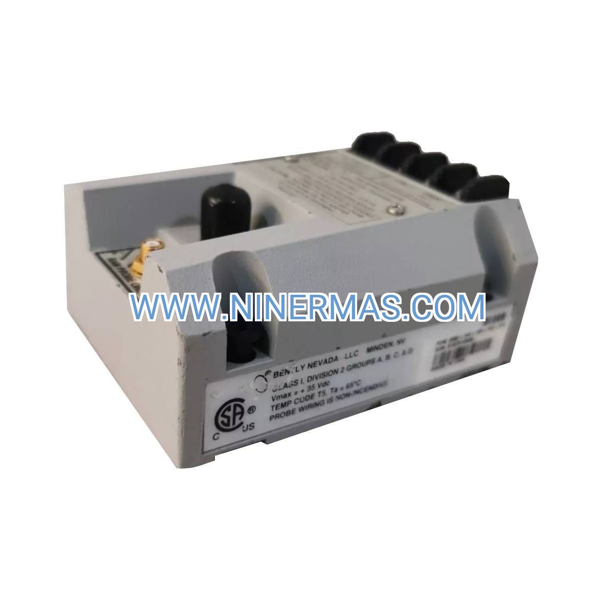
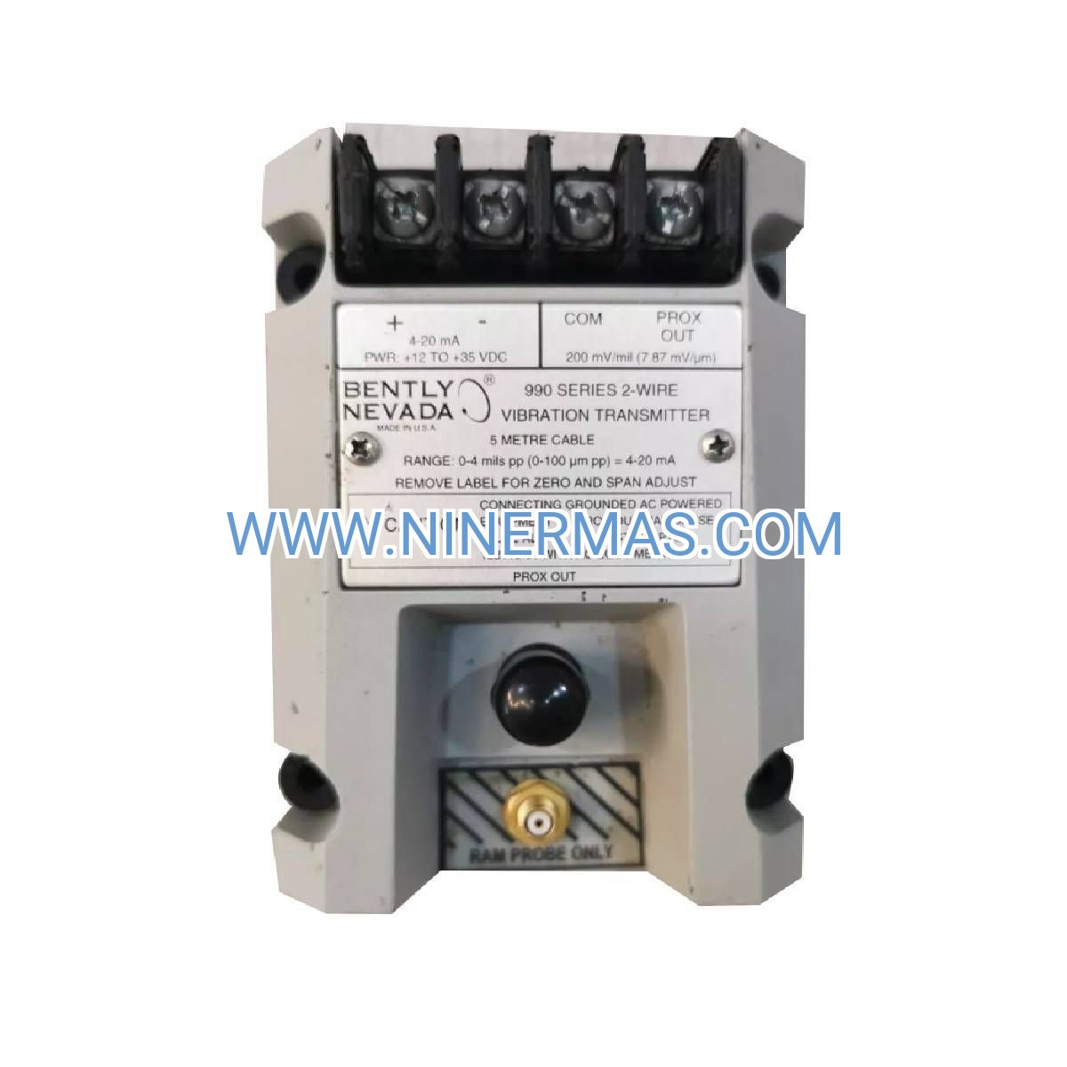
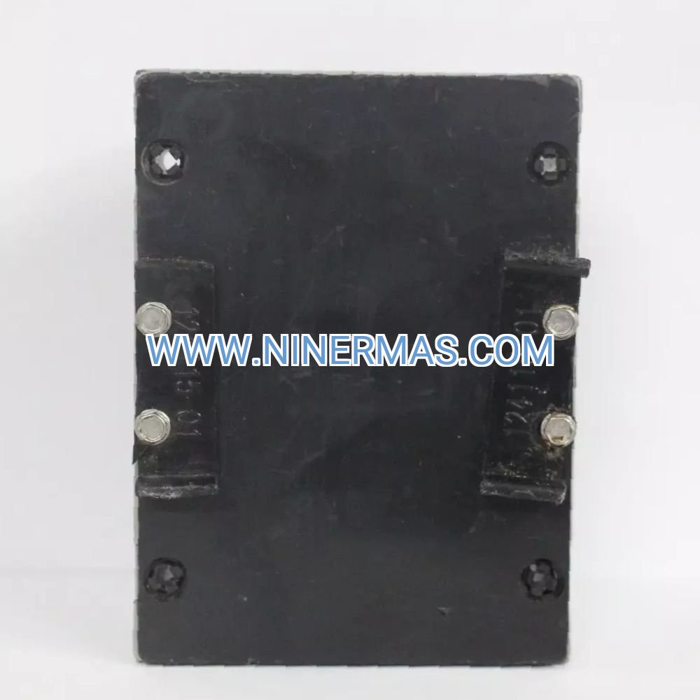
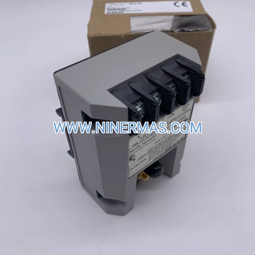
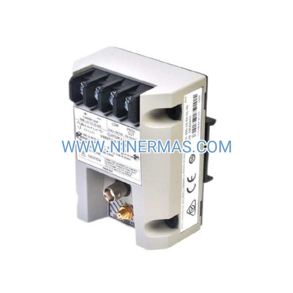
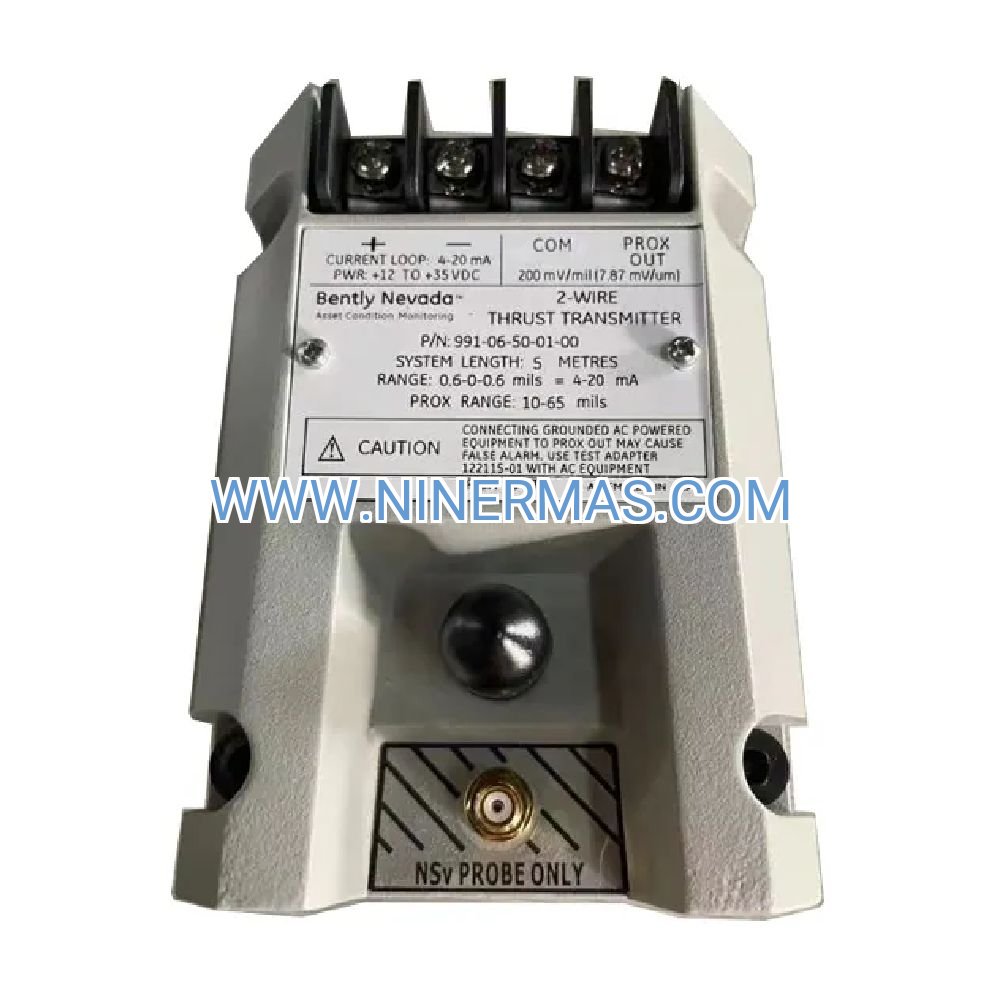
990-05-50-01-01 Industrial Vibration Transmitter (Loop-Powered Condition Monitor)
The 990-05-50-01-01 represents a field-proven solution for continuous vibration surveillance in mission-critical rotating machinery. Engineered with loop-powered architecture and standardized 4-20 mA current output, this transmitter seamlessly integrates into existing PLC, DCS, and SCADA infrastructures without requiring dedicated power circuits. Designed for OEM equipment manufacturers and plant maintenance teams, it delivers consistent performance across temperature extremes from -40°C to +85°C while maintaining IP67 environmental protection.
Industrial facilities operating centrifugal compressors, process pumps, and high-speed motors rely on this transmitter to detect early-stage mechanical degradation—including bearing wear, shaft misalignment, and rotor imbalance—before catastrophic failures occur. The factory-calibrated 0-50 mm/s velocity range aligns with ISO 20816 severity guidelines, enabling direct comparison against industry-accepted vibration thresholds for proactive maintenance scheduling.
With API 670 conformity and stainless steel construction, the 990-05-50-01-01 meets stringent requirements for petrochemical, power generation, and heavy manufacturing environments where equipment uptime directly impacts production revenue and operational safety.
Key Technical Features & Industrial Value
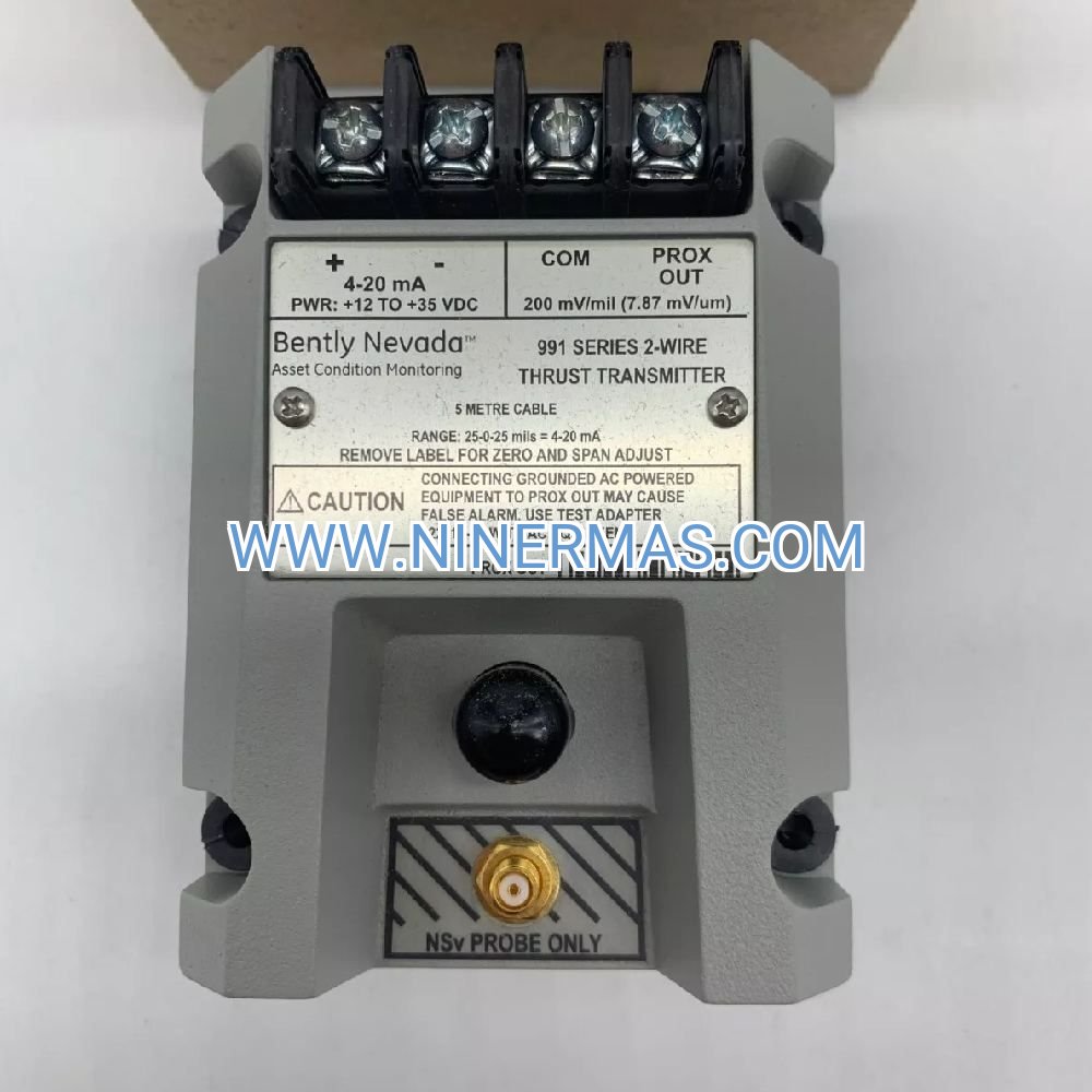
→ Loop-Powered 4-20 mA Architecture
Eliminates separate power supply requirements; draws operating current directly from control system input cards. Reduces installation costs by 30-40% compared to externally-powered sensors while simplifying wiring in hazardous area classifications.
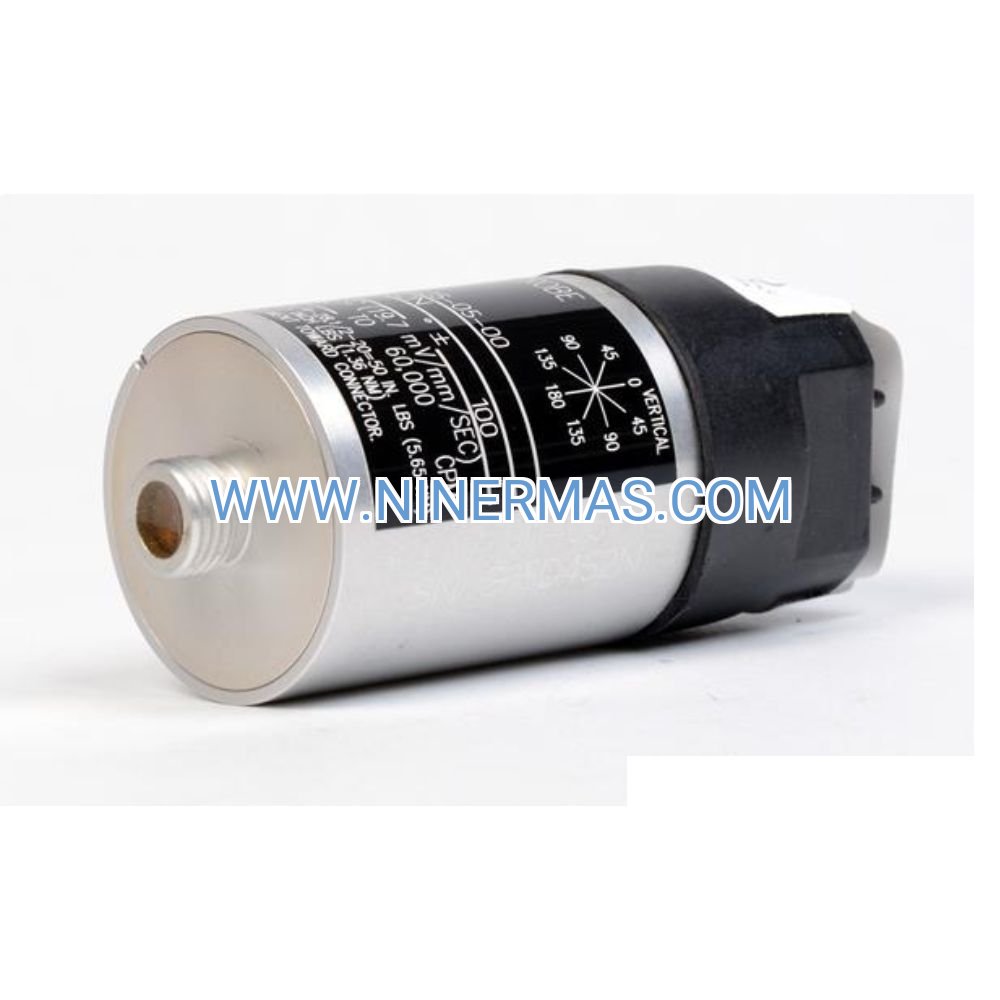
→ 0-50 mm/s Velocity Measurement Range
Optimized for detecting common machinery faults in the 10-1000 Hz frequency band. Velocity measurement provides superior sensitivity to bearing defects, unbalance, and looseness compared to displacement or acceleration-only sensors.
→ API 670 Machinery Protection Compliance
Meets American Petroleum Institute standards for vibration monitoring systems in critical service applications. Ensures compatibility with safety instrumented systems (SIS) and emergency shutdown logic in refineries and chemical plants.
✓ Extended Temperature Performance (-40°C to +85°C)
Maintains measurement accuracy across extreme ambient conditions found in outdoor installations, desert climates, and high-temperature process areas. Thermal stability prevents false alarms caused by environmental fluctuations.
✓ IP67 Sealed Stainless Steel Housing
Provides complete protection against dust ingress and temporary water immersion during washdown procedures. Corrosion-resistant construction extends service life in chemical processing and marine environments.
✓ Factory Calibration with NIST-Traceable Certification
Each unit ships with documented calibration data verifying output linearity, frequency response, and zero offset. Reduces commissioning time and ensures measurement integrity for quality management systems (ISO 9001, AS9100).
Industrial Application Scenarios
Centrifugal Compressor Monitoring
Installed on compressor casings in natural gas processing and air separation plants, the transmitter continuously tracks bearing housing vibration. Early detection of elevated velocity levels triggers maintenance interventions before bearing seizure causes unplanned shutdowns costing $50,000-$500,000 per incident in lost production.
Process Pump Condition Surveillance
Mounted on pump pedestals in chemical transfer and water treatment systems, the sensor identifies cavitation, impeller damage, and seal wear through characteristic vibration signatures. Predictive maintenance programs using this data reduce pump failure rates by 60-75% compared to reactive repair strategies.
Electric Motor Health Monitoring
Attached to motor bearing caps in conveyor drives, agitators, and fan systems, the transmitter detects rotor bar cracks, stator winding faults, and coupling misalignment. Integration with motor control centers enables automated load shedding or shutdown when vibration exceeds alarm thresholds.
Turbine-Generator Protection
Deployed on steam turbine casings and generator bearing housings in power plants, the sensor provides continuous vibration data to turbine supervisory systems. Compliance with NERC reliability standards requires this level of monitoring for grid-connected generating assets above 20 MW capacity.
HVAC Equipment Diagnostics
Applied to large chiller compressors and cooling tower fan bearings in commercial facilities, the transmitter supports energy management programs by identifying mechanical inefficiencies that increase power consumption by 15-25% before total equipment failure.
Technical Parameters & Selection Guide
| Parameter | Specification | Selection Notes |
|---|---|---|
| Model Designation | 990-05-50-01-01 | Factory configuration code |
| Measurement Type | Vibration Velocity | Optimal for 10-1000 Hz machinery faults |
| Velocity Range | 0-50 mm/s RMS | Covers ISO 20816 zones A-D for most equipment |
| Output Signal | 4-20 mA current loop | 2-wire loop-powered configuration |
| Frequency Response | 10 Hz - 1 kHz (±3 dB) | Captures bearing tones and blade pass frequencies |
| Power Requirement | 18-30 VDC loop supply | Typical consumption: 3.5 mA @ 24 VDC |
| Operating Temperature | -40°C to +85°C | Suitable for outdoor and high-temp installations |
| Environmental Rating | IP67 (dust-tight, water immersion) | Washdown-compatible for food/pharma applications |
| Housing Material | 316 stainless steel | Corrosion resistance for chemical environments |
| Mounting Thread | M12 x 1.5 or 1/4-28 UNF | Specify thread type when ordering |
| Cable Connection | Integral 3-meter cable | Custom lengths available on request |
| Compliance Standards | API 670, ISO 20816, CE | Meets global machinery protection requirements |
Selection Criteria: Choose this model when monitoring general-purpose rotating equipment with shaft speeds between 600-3600 RPM. For higher frequency applications (gearboxes, rolling element bearings above 10 kHz), consider acceleration-output models. For equipment requiring displacement measurement (large turbines, journal bearings), proximity probe systems are recommended.
Advanced Integration Capabilities
SCADA & Historian Connectivity
The 4-20 mA output directly interfaces with Modbus RTU, HART, and Foundation Fieldbus converters for enterprise-level data aggregation. Trend analysis in OSIsoft PI, Wonderware, or Ignition platforms enables correlation between vibration patterns and process variables (temperature, pressure, flow rate) to identify root causes of equipment degradation.
Wireless Monitoring Adaptation
When paired with analog-to-wireless gateway modules (WirelessHART, ISA100), the transmitter supports remote monitoring in areas where cable installation is cost-prohibitive. Battery-powered wireless nodes can operate 3-5 years on a single charge when sampling vibration data every 15 minutes.
Machine Learning Integration
Vibration data streams from multiple transmitters feed into cloud-based analytics platforms (AWS IoT, Azure Industrial IoT) where AI algorithms detect anomalous patterns invisible to threshold-based alarming. Predictive models forecast remaining useful life (RUL) with 85-90% accuracy for bearing and gearbox failures.
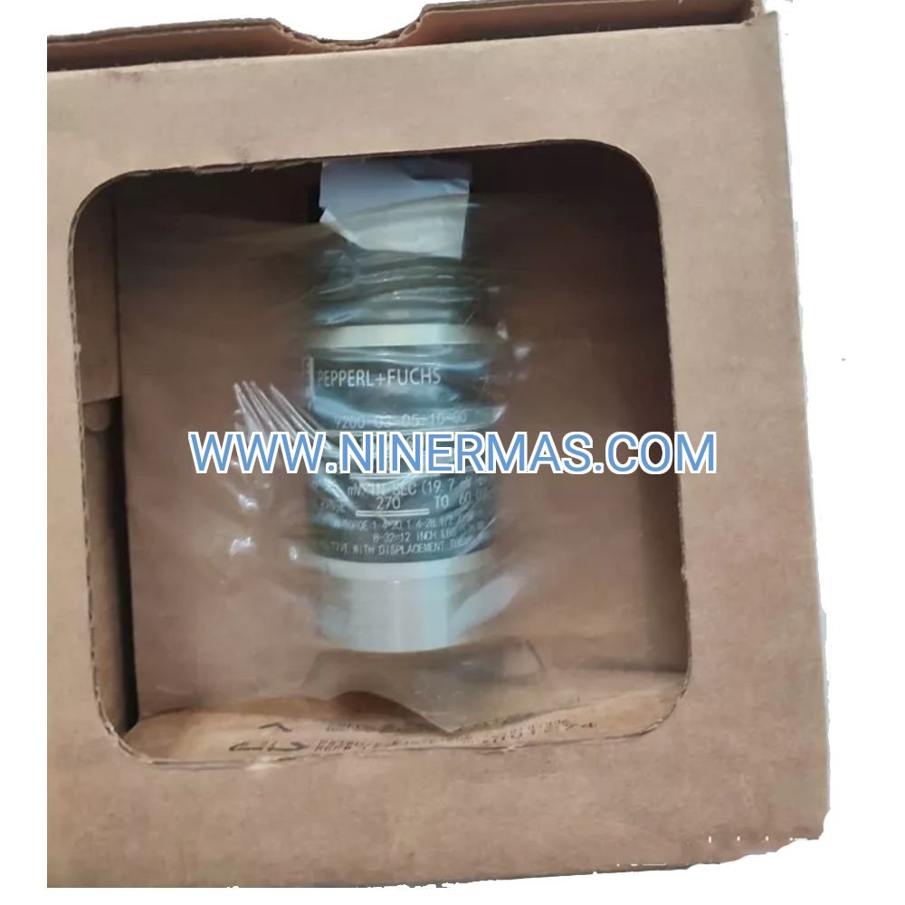
Delivery Timeline & Service Commitments
Standard Lead Time: 3-5 business days for stock configurations; 10-15 business days for custom cable lengths or special mounting adapters
Warranty Coverage: 12-month manufacturer defect warranty from shipment date; extended warranties available for critical service applications
Technical Support: Application engineering assistance for sensor placement, mounting torque specifications, and output scaling calculations
Documentation Package: Includes calibration certificate, dimensional drawings, wiring diagrams, and integration guide for common PLC platforms (Allen-Bradley, Siemens, Schneider Electric)
Frequently Asked Questions
How does loop-powered operation differ from self-powered accelerometers?
Loop-powered transmitters draw operating current from the control system's 24 VDC supply through the same two wires that carry the 4-20 mA signal. This eliminates battery replacement (required in self-powered sensors every 2-4 years) and simplifies installation in intrinsically safe (IS) circuits. The tradeoff is slightly higher current consumption (3-4 mA) compared to IEPE accelerometers.
Can this transmitter detect high-frequency bearing defects above 1 kHz?
The 10 Hz - 1 kHz frequency response is optimized for overall vibration severity measurement per ISO 20816. For bearing fault detection requiring analysis above 5 kHz (rolling element defect frequencies), use acceleration-output sensors with 20+ kHz bandwidth. However, 80% of machinery failures exhibit symptoms within this transmitter's measurement range.
What mounting torque should be applied to ensure accurate readings?
Apply 15-20 Nm (11-15 ft-lbs) for M12 threads or 8-10 Nm (6-7 ft-lbs) for 1/4-28 UNF threads. Use a calibrated torque wrench and apply thread sealant (Loctite 567 or equivalent) to prevent loosening from vibration. Under-torquing causes resonance amplification; over-torquing risks thread damage and housing distortion.
Is annual recalibration required for ISO 9001 compliance?
ISO 9001 does not mandate specific calibration intervals—your quality management system defines requirements based on risk assessment. Most facilities recalibrate vibration transmitters every 12-24 months. The sensor's solid-state design exhibits minimal drift (typically <2% over 5 years), so extended intervals are acceptable for non-critical applications.
How do I convert the 4-20 mA signal to engineering units in my PLC?
Use this scaling formula: Vibration (mm/s) = [(Current - 4 mA) / 16 mA] × 50 mm/s. For example, 12 mA output = [(12-4)/16] × 50 = 25 mm/s. Most PLCs have built-in scaling blocks (SCL in Siemens, SCP in Allen-Bradley) that perform this calculation automatically when you enter the 4-20 mA range and 0-50 mm/s engineering limits.
Can multiple transmitters share a single power supply?
Yes, if using isolated 4-20 mA input cards. Each transmitter requires a dedicated current loop, but all loops can reference a common 24 VDC power rail. Ensure the power supply has sufficient capacity (minimum 50 mA per transmitter) and use individual loop resistors (typically 250Ω) at the PLC input to convert current to voltage for A/D conversion.
Take the Next Step in Machinery Protection
Protect your critical assets with proven vibration monitoring technology. Contact our application engineers to discuss sensor placement strategies, integration with your existing control systems, and volume pricing for multi-unit installations. Request a detailed datasheet with mounting dimensions and wiring schematics, or order your 990-05-50-01-01 transmitter today with expedited shipping options available.
© 2026 NINERMAS COMPANY LIMITED. All rights reserved.
Original Source: https://ninermas.com
Contact: sale@ninermas.com | +0086 187 5021 5667
PDF Specification
Download PDF file here:
Click to Download PDF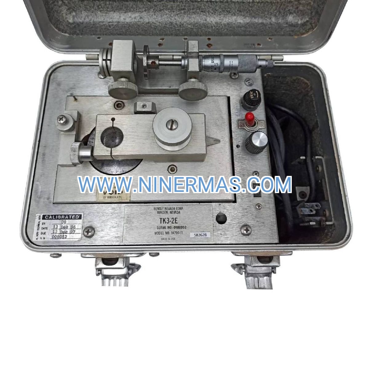

Contact Info
-
Address:22 / F, South Wo Hang building, 148 Wing Lok Street, Sheung Wan, Western District, Hong Kong
-
Phone:+8618750215667
-
Email: