

Description
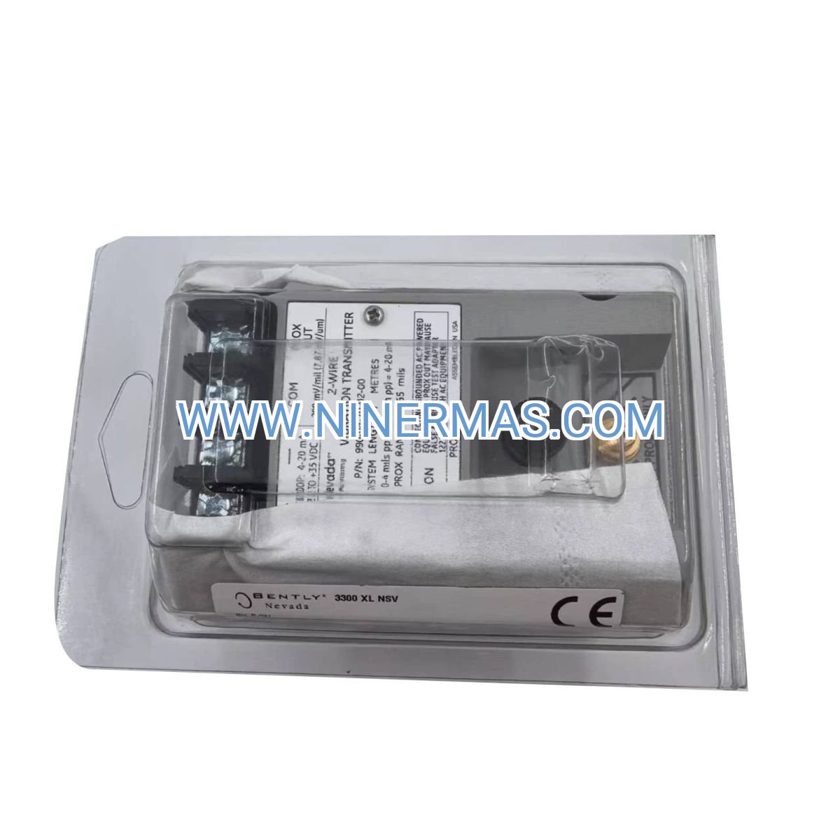
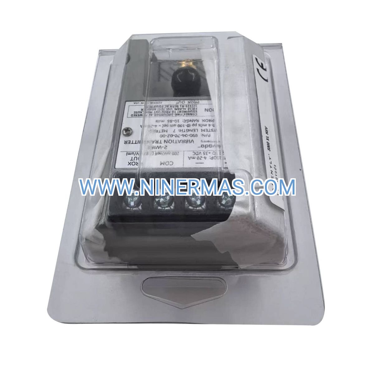
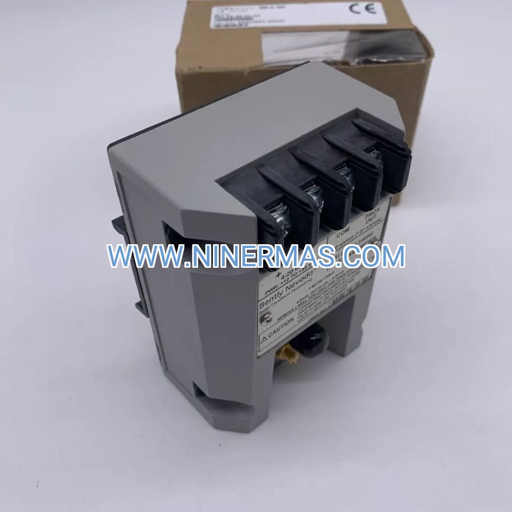
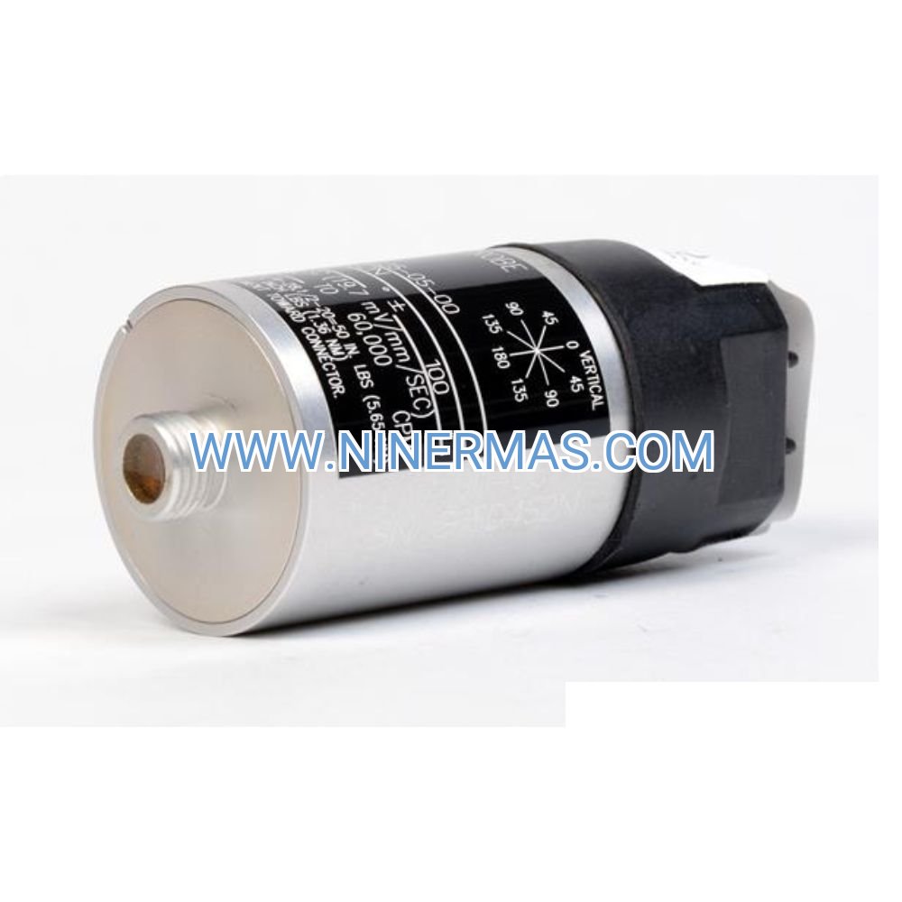
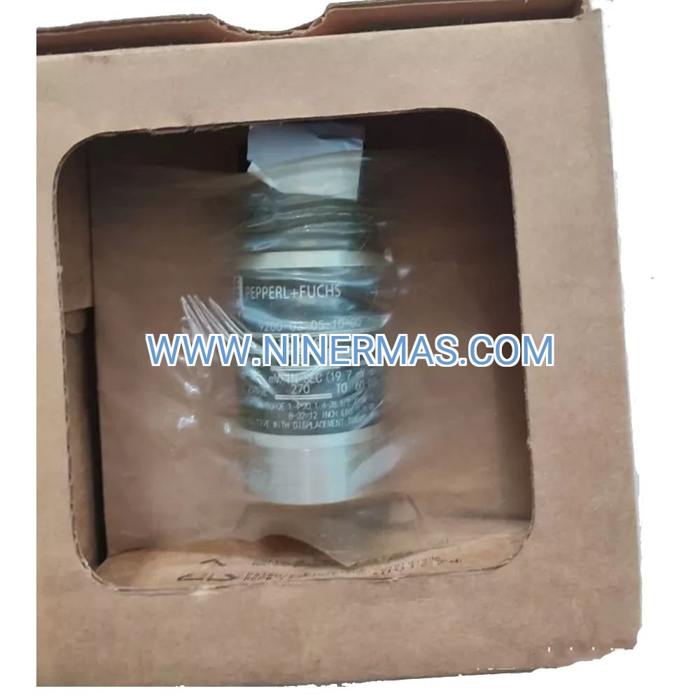
990-04-70-02-00 Vibration Transmitter – Industrial-Grade Machinery Monitoring Solution
The 990-04-70-02-00 vibration transmitter is a precision-engineered condition monitoring device designed for continuous vibration measurement on rotating machinery. Utilizing an integrated piezoelectric accelerometer with advanced signal conditioning, it delivers a standardized 4-20 mA analog output proportional to vibration velocity, enabling seamless integration with DCS, PLC, SCADA, and plant-wide monitoring systems.
Engineered for harsh industrial environments, this transmitter addresses critical challenges in machinery health management: unpredictable equipment failures, excessive maintenance costs, and unplanned production downtime. It is widely deployed across power generation facilities, petrochemical complexes, manufacturing plants, and offshore platforms where equipment reliability directly impacts operational safety and profitability.
Through factory-calibrated accuracy and rugged IP67-rated construction, the 990-04-70-02-00 provides reliable early-warning detection of bearing degradation, shaft misalignment, rotor unbalance, and mechanical looseness. Suitable for design engineers, maintenance managers, system integrators, and plant operators seeking to transition from reactive to predictive maintenance strategies. Contact our application engineers for customized selection guidance, calibration certificates, and technical documentation.
Core Features & Technical Advantages
Precision Velocity Measurement
Factory-calibrated to measure vibration velocity from 0 to 70 mm/s (0 to 2.76 in/s) across a frequency bandwidth of 10 Hz to 1000 Hz, covering the critical range for general machinery fault detection per ISO 20816 and ISO 10816 standards. Velocity measurement provides superior correlation to mechanical stress and damage potential compared to displacement or acceleration alone.
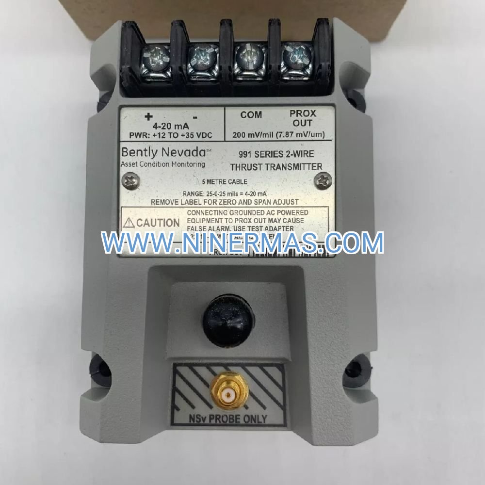
Universal 4-20 mA Loop Integration
Two-wire loop-powered design eliminates the need for separate power supplies. The transmitter draws operating current from the 4-20 mA signal loop (12-30 VDC supply), simplifying installation and reducing wiring costs. Output signal is directly compatible with standard PLC analog input cards, chart recorders, and distributed control systems without additional signal conditioning.
Robust Environmental Protection
Stainless steel housing with IP67 ingress protection withstands exposure to moisture, dust, oil mist, and temperature extremes from -40°C to +85°C (-40°F to +185°F). Hermetically sealed electronics prevent contamination in corrosive atmospheres typical of chemical processing, offshore drilling, and heavy manufacturing environments.
Comprehensive Fault Detection Capability
Detects multiple machinery fault signatures including: bearing wear (high-frequency energy increase), rotor unbalance (1× running speed amplitude), misalignment (2× and 3× harmonics), looseness (broad-spectrum energy), and resonance conditions. Early detection enables condition-based maintenance scheduling, reducing emergency repair costs by up to 40% and extending mean time between failures (MTBF).
Simplified Installation & Commissioning
Standard 1/4-28 UNF mounting thread fits industry-standard sensor mounting pads and magnetic bases. Pre-calibrated at the factory with traceable certification eliminates field calibration requirements. Plug-and-play operation reduces commissioning time from hours to minutes, minimizing installation labor and startup delays.
Long-Term Stability & Reliability
Solid-state accelerometer technology with no moving parts ensures measurement stability over multi-year service intervals. Designed for continuous operation in 24/7 industrial environments with MTBF exceeding 100,000 hours. Low drift characteristics maintain calibration accuracy within ±5% over the product lifecycle.
Typical Application Scenarios
The 990-04-70-02-00 transmitter is engineered for demanding applications where machinery reliability and uptime are critical to operational success:
Turbomachinery & Rotating Equipment
Continuous monitoring of gas turbines, steam turbines, centrifugal compressors, axial compressors, and turboexpanders in power generation, oil & gas processing, and petrochemical facilities. Provides real-time vibration trending to detect degradation before catastrophic failure, protecting assets valued at millions of dollars and preventing extended outages.
Pumps & Motor-Driven Systems
Condition monitoring of centrifugal pumps, positive displacement pumps, electric motors, cooling tower fans, and induced draft fans in water treatment plants, HVAC systems, chemical processing, and pulp & paper mills. Enables transition from time-based to condition-based maintenance, reducing unnecessary bearing replacements and optimizing spare parts inventory.
Power Generation & Cogeneration Plants
Protection of generator sets, turbine-generator units, boiler feed pumps, condensate pumps, and auxiliary equipment in coal-fired, combined-cycle, nuclear, and renewable energy facilities. Compliance with API 670 machinery protection standards and integration with plant DCS for automated shutdown and alarm management.
Oil, Gas & Petrochemical Processing
Offshore platform equipment monitoring, refinery process pumps, pipeline compressor stations, LNG liquefaction trains, and floating production storage offloading (FPSO) vessels. Harsh environment capability with extended temperature range and corrosion-resistant materials ensures reliable operation in marine and hazardous area installations.
Heavy Manufacturing & Material Processing
Steel mill rolling stands, paper machine dryer sections, cement kiln drives, mining conveyors, and industrial gearboxes. High vibration tolerance and rugged construction withstand shock loads and extreme operating conditions typical of primary metals, mining, and bulk material handling industries.
Technical Specifications & Selection Parameters
To facilitate accurate system design and product selection, the following specifications define the operational envelope and interface requirements:
| Parameter | Specification | Notes |
|---|---|---|
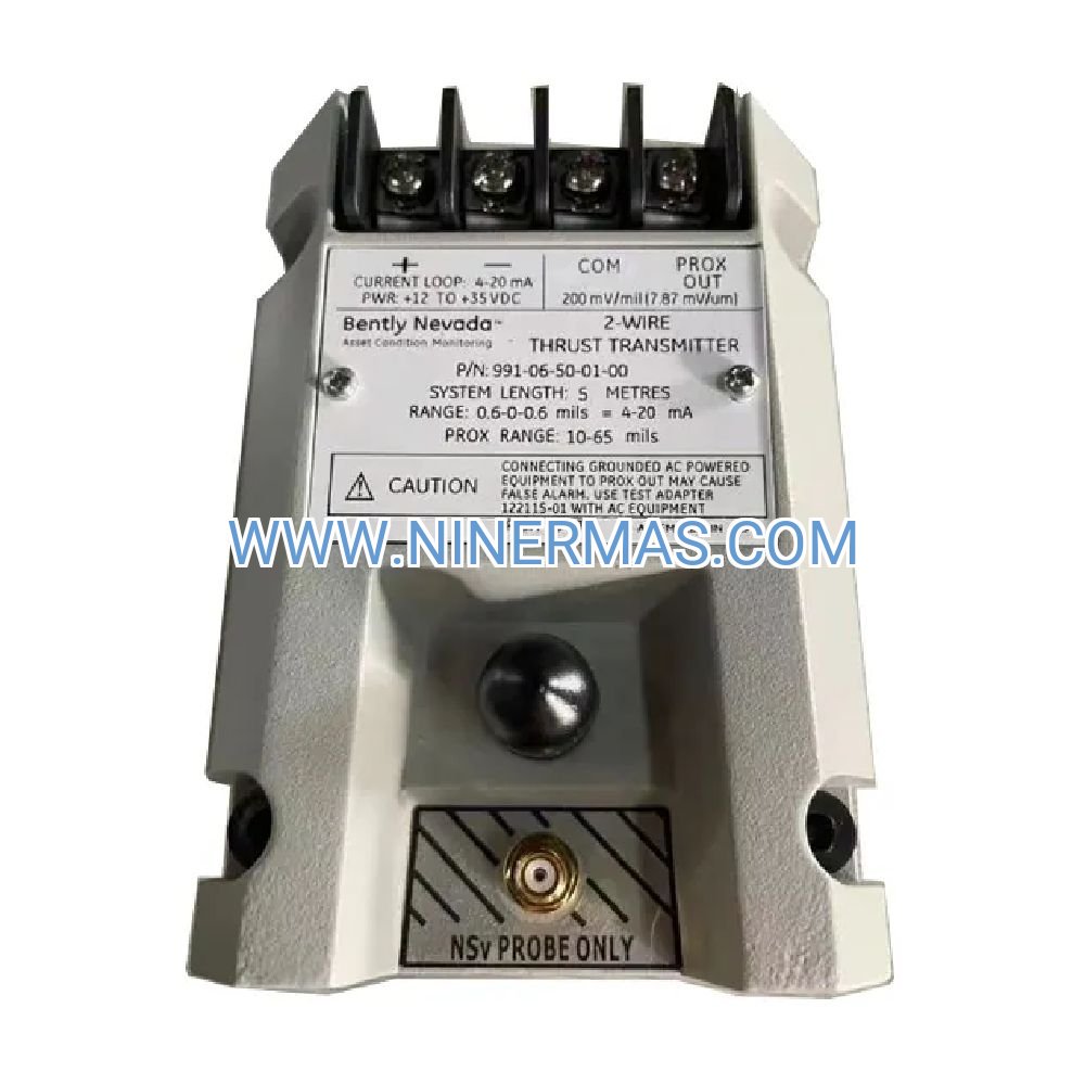
| Model Number | 990-04-70-02-00 | Factory designation |
| Measurement Type | Vibration Velocity (RMS) | ISO 10816 compliant |
| Measurement Range | 0 - 70 mm/s (0 - 2.76 in/s) | Velocity, RMS |
| Frequency Response | 10 Hz - 1000 Hz (±3 dB) | Covers machinery faults |
| Output Signal | 4-20 mA DC | Loop-powered, 2-wire |
| Loop Supply Voltage | 12 - 30 VDC | Typical 24 VDC |
| Maximum Loop Resistance | 750 Ω @ 24 VDC | Consult datasheet for other voltages |
| Accuracy | ±5% of full scale | At calibration conditions |
| Operating Temperature | -40°C to +85°C (-40°F to +185°F) | Extended range available |
| Storage Temperature | -50°C to +90°C | Non-operating |
| Housing Material | 316 Stainless Steel | Corrosion resistant |
| Ingress Protection | IP67 (IEC 60529) | Dust-tight, water immersion |
| Mounting Thread | 1/4-28 UNF | Standard sensor mount |
| Electrical Connection | 2-pin MS connector or cable gland | Specify at order |
| Weight | Approx. 200 g (0.44 lb) | Excluding cable |
| Compliance Standards | API 670, ISO 20816, CE marked | Machinery protection standards |
Selection Guidance for System Designers
When specifying the 990-04-70-02-00 transmitter for your application, consider the following system parameters to ensure optimal performance:
- Vibration Level Assessment: Verify that expected machinery vibration levels fall within the 0-70 mm/s measurement range. For higher vibration applications (>70 mm/s), consult our engineering team for extended-range models.
- Frequency Content Analysis: Confirm that critical fault frequencies lie within the 10-1000 Hz bandwidth. For high-speed machinery (>10,000 RPM) requiring extended frequency response, alternative accelerometer-output models may be recommended.
- Loop Power Budget: Calculate total loop resistance including cable resistance and input card burden. For long cable runs (>500 m), higher supply voltages or signal repeaters may be required.
- Environmental Conditions: Assess ambient temperature, humidity, chemical exposure, and vibration/shock levels at the mounting location. For hazardous area installations (ATEX Zone 1/2, IECEx, or NEC Division 1/2), specify intrinsically safe (IS) certified versions.
- Mounting Configuration: Determine mounting method (direct stud mount, magnetic base, or adhesive mount) based on surface accessibility, temperature, and required measurement fidelity.
For application-specific selection assistance, provide our engineering team with: equipment type and model, operating speed (RPM), expected vibration levels, ambient conditions, and control system interface requirements. We will recommend the optimal transmitter configuration and provide certified calibration documentation.
Advanced Integration & Monitoring Capabilities
DCS & SCADA System Integration
The 4-20 mA output interfaces directly with analog input modules from major automation vendors including Honeywell, Emerson DeltaV, Siemens PCS 7, Rockwell PlantPAx, and Yokogawa Centum. Configure alarm setpoints and trending functions within your existing HMI/SCADA platform for centralized machinery health monitoring across multiple assets.
PLC-Based Monitoring & Protection
Connect to standard PLC analog input cards (Allen-Bradley, Siemens S7, Schneider Modicon, Mitsubishi, Omron) for local vibration monitoring and automated shutdown logic. Implement multi-stage alarm thresholds (alert, alarm, danger, trip) based on ISO 20816 severity criteria or equipment manufacturer recommendations.
Portable Data Collectors & Route-Based Monitoring
While the transmitter provides continuous online monitoring, it can complement route-based vibration programs using portable analyzers. The fixed installation point ensures consistent measurement location for trending analysis and comparison with handheld data collection.
Wireless Monitoring Solutions
For retrofit applications or remote locations, the 4-20 mA output can interface with wireless I/O modules (WirelessHART, ISA100, LoRaWAN) to transmit vibration data to cloud-based condition monitoring platforms without extensive cabling infrastructure.
Delivery, Calibration & Technical Support
Lead Time & Availability
Standard 990-04-70-02-00 transmitters with factory-default configuration ship from stock within 3-5 business days. Custom calibration ranges, special cable lengths, or hazardous area certifications require 2-3 weeks for engineering and certification documentation. Expedited processing available for critical outage situations.
Quality Assurance & Calibration
Every transmitter undergoes multi-point calibration traceable to NIST standards before shipment. Included documentation package contains: calibration certificate with test data, frequency response curve, installation instructions, dimensional drawings, and electrical wiring diagrams. Optional ISO 17025 accredited calibration available upon request.
Warranty Coverage
All units carry a 24-month manufacturer warranty covering defects in materials and workmanship under normal operating conditions. Warranty includes free repair or replacement, return shipping, and recalibration services. Extended warranty programs available for critical applications requiring guaranteed uptime.
Technical Support Services
Our vibration monitoring specialists provide comprehensive application support including: sensor placement recommendations, mounting hardware selection, cable specification, signal conditioning guidance, alarm setpoint calculation, and troubleshooting assistance. Remote diagnostic support and on-site commissioning services available in select regions.
Training & Documentation
Complimentary access to online resources including installation videos, application notes, troubleshooting guides, and vibration analysis fundamentals. Custom training programs available for maintenance teams transitioning to condition-based monitoring strategies.
Frequently Asked Questions (FAQ)
Q: What is the difference between vibration velocity, displacement, and acceleration measurements?
A: Velocity (mm/s) is the preferred parameter for general machinery monitoring per ISO 10816 standards because it correlates best with mechanical stress and damage across typical operating frequencies (10-1000 Hz). Displacement (µm) is used for low-speed machinery (<600 RPM) and shaft relative motion. Acceleration (g) is preferred for high-frequency bearing diagnostics and impact detection. The 990-04-70-02-00 measures velocity, making it ideal for pumps, motors, fans, and general rotating equipment.
Q: Can this transmitter be used in hazardous area (explosive atmosphere) installations?
A: The standard 990-04-70-02-00 model is not intrinsically safe certified. For installations in ATEX Zone 1/2, IECEx, or NEC Class I Division 1/2 hazardous areas, specify the intrinsically safe (IS) certified version at time of order. IS models include barrier/isolator requirements and certification documentation for compliance with local regulations.
Q: What is the maximum cable length between the transmitter and control system input card?
A: Maximum cable length depends on loop supply voltage and total loop resistance. With 24 VDC supply and maximum 750 Ω loop resistance, typical installations support 500-800 meters using 18 AWG (0.75 mm²) shielded twisted pair cable. For longer distances, use higher supply voltage (up to 30 VDC) or install signal repeaters/isolators. Contact our engineering team for cable length calculations specific to your installation.
Q: How does the 4-20 mA output scale to vibration velocity?
A: The transmitter is factory-calibrated so that 4 mA represents 0 mm/s vibration and 20 mA represents 70 mm/s vibration (full scale). The relationship is linear: each 1 mA increment equals 4.375 mm/s. For example, 12 mA output indicates 35 mm/s vibration velocity. Custom scaling ranges can be specified at time of order for applications requiring different measurement spans.
Q: What mounting hardware and accessories are required for installation?
A: The transmitter requires a mounting stud or pad with 1/4-28 UNF threaded hole. Common mounting methods include: (1) permanent stud mount welded or drilled into machinery casing, (2) magnetic mounting base for temporary or portable installations, (3) adhesive mounting pad for non-ferrous surfaces. Mounting hardware, cable assemblies, and junction boxes are sold separately. Consult our accessory catalog or contact sales for complete installation kits.
Q: Can multiple transmitters share the same power supply and monitoring system?
A: Yes, each transmitter operates on an independent 4-20 mA loop. A single 24 VDC power supply can power multiple loops through individual current-limiting resistors or dedicated loop-powered input cards. Ensure adequate power supply capacity (typically 25-30 mA per loop) and proper electrical isolation between channels to prevent ground loops and signal interference.
Q: What is the recommended calibration interval for maintaining measurement accuracy?
A: Under normal operating conditions, recalibration is recommended every 2-3 years to verify measurement accuracy within specification. For critical applications or harsh environments (extreme temperatures, high shock/vibration, corrosive atmospheres), annual calibration may be advisable. We offer factory recalibration services with NIST-traceable certification and expedited turnaround for minimal downtime.
Request Custom Selection & Technical Quotation
To receive a tailored transmitter recommendation, detailed technical proposal, and competitive pricing for your machinery monitoring project, please provide the following information to our application engineering team:
- Project Overview: Facility name, location, application type (new installation, retrofit, expansion)
- Equipment Details: Machinery type (pump, motor, turbine, etc.), manufacturer, model, operating speed (RPM)
- Vibration Parameters: Expected vibration levels (if known), critical fault frequencies, measurement objectives
- Quantity Requirements: Number of monitoring points, single unit or volume procurement
- Environmental Conditions: Ambient temperature range, hazardous area classification (if applicable), exposure to moisture/chemicals
- System Integration: Control system type (DCS, PLC, SCADA), input card specifications, preferred cable length and connector type
- Delivery Schedule: Required delivery date, installation timeline, commissioning support needs
Our engineers will respond within 24 hours with a comprehensive solution proposal including: transmitter model selection, mounting recommendations, cable specifications, calibration options, pricing, and delivery schedule.
© 2026 NINERMAS COMPANY LIMITED. All rights reserved.
Original Source: https://ninermas.com
Contact: sale@ninermas.com | +0086 187 5021 5667

Contact Info
-
Address:22 / F, South Wo Hang building, 148 Wing Lok Street, Sheung Wan, Western District, Hong Kong
-
Phone:+8618750215667
-
Email: