
Bently Nevada 84157-01 Relay Board | 3300 Series Vibration Monitor Module | NINERMAS
Description
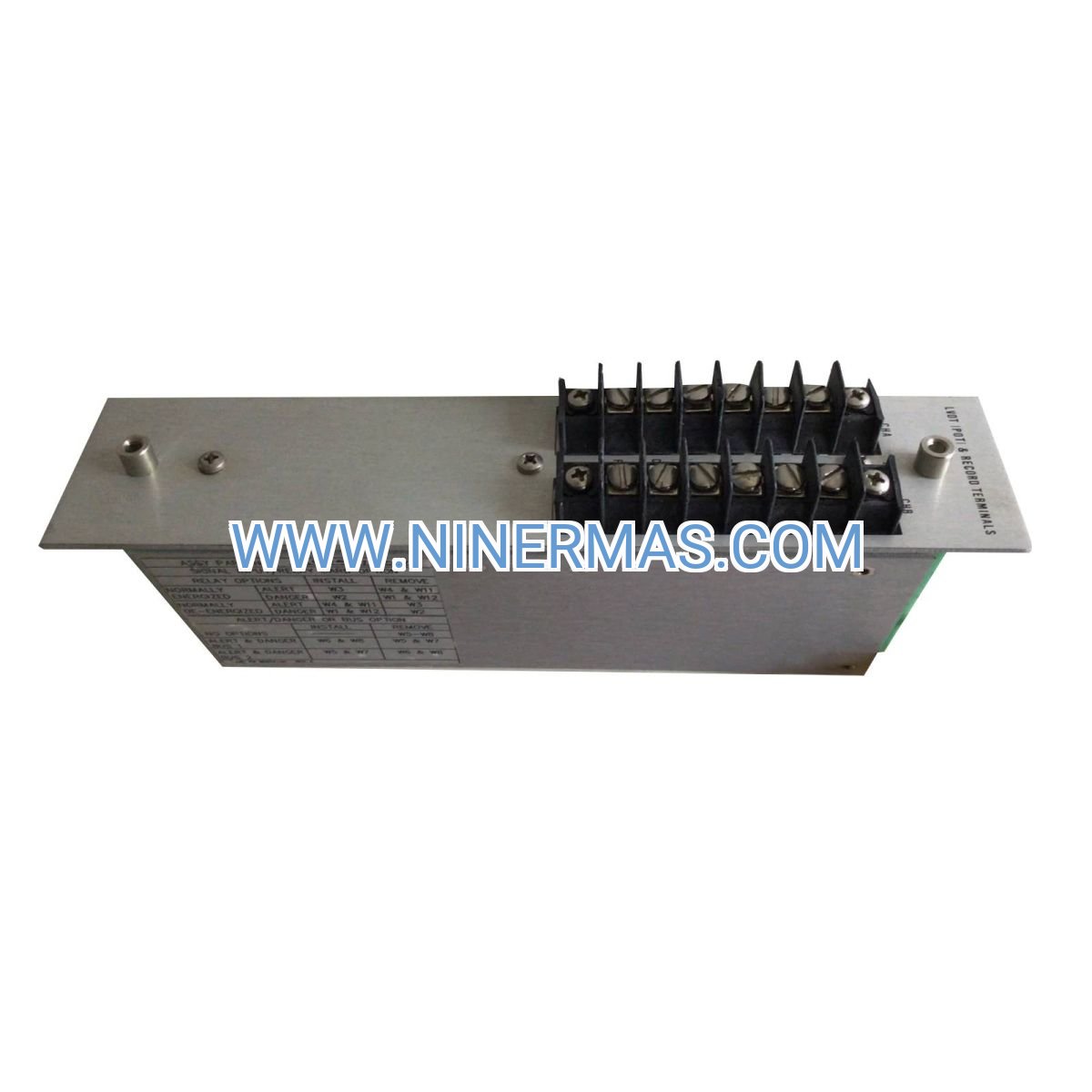
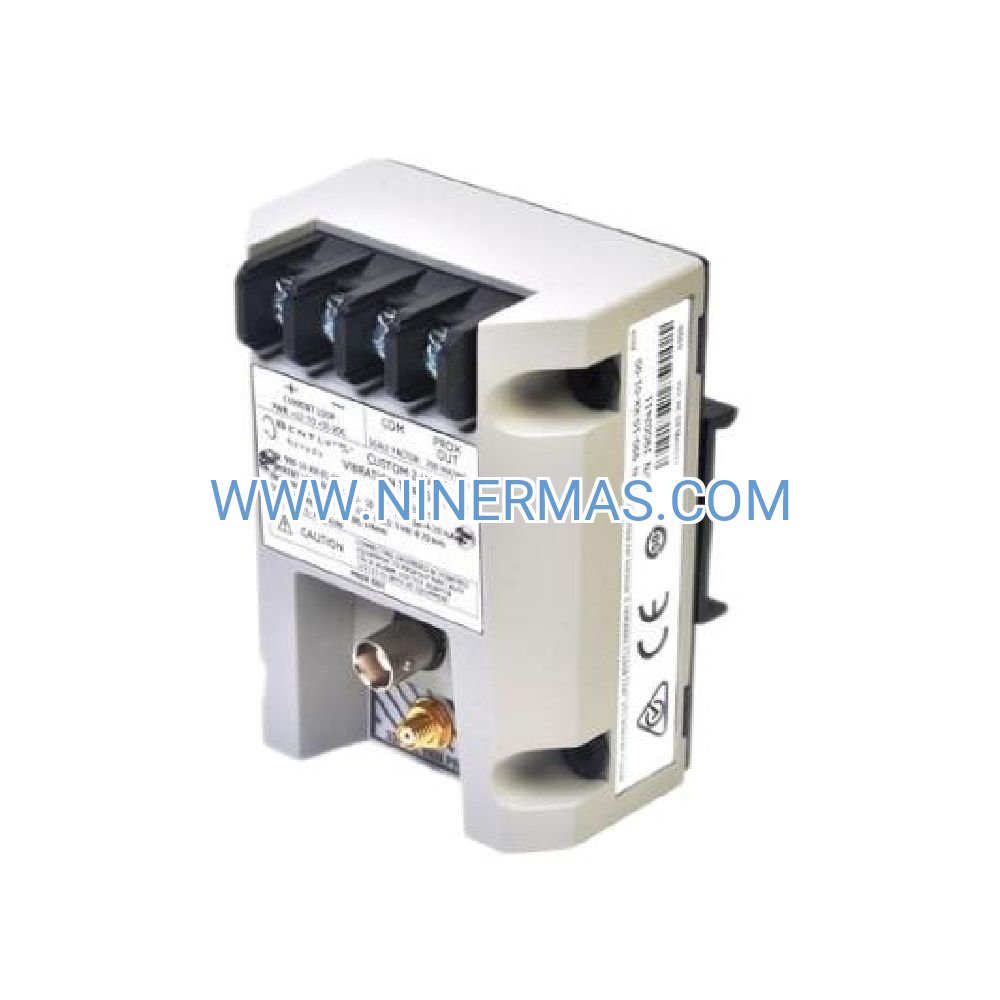
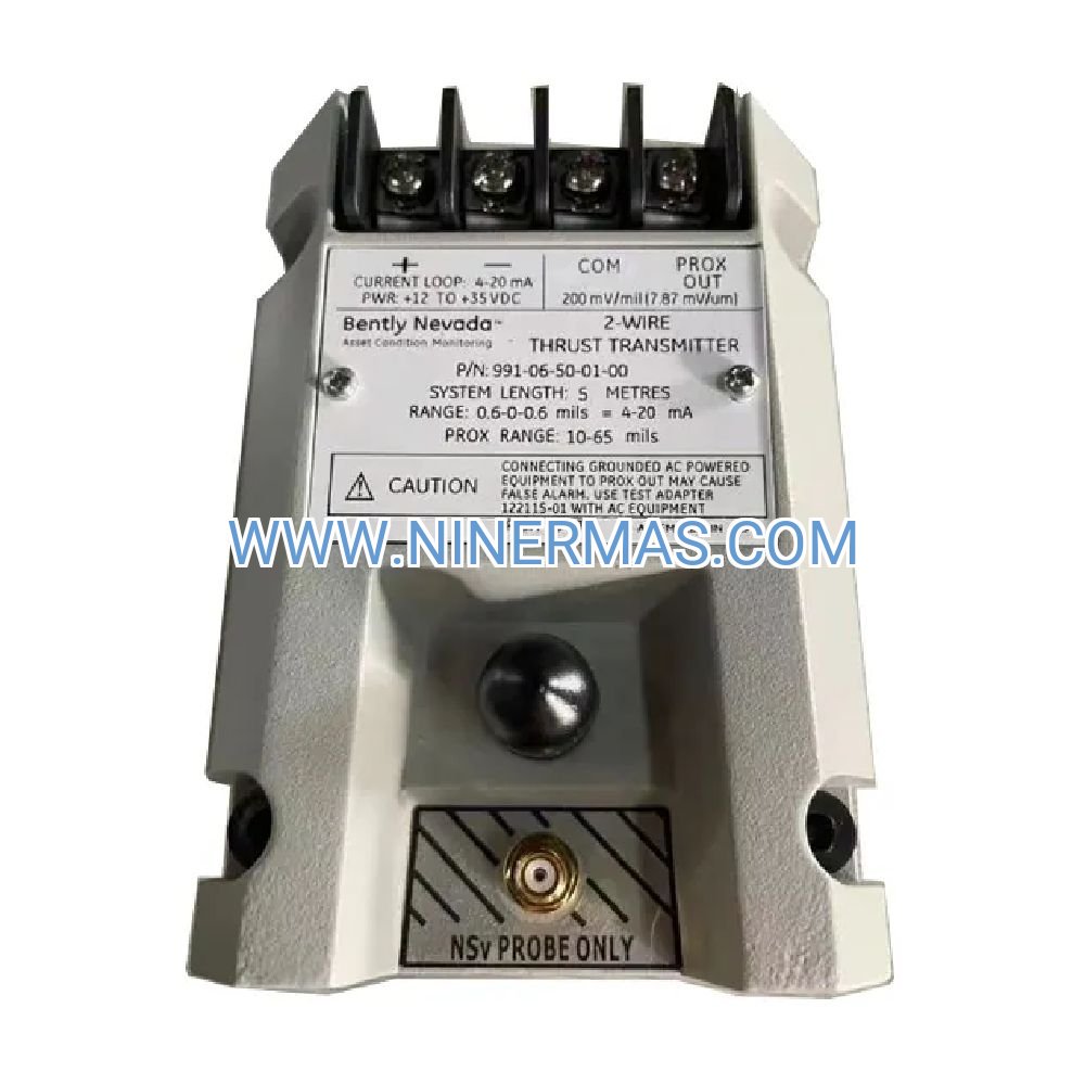
84157-01 Vibration Relay Board (Industrial-Grade Alarm Interface)
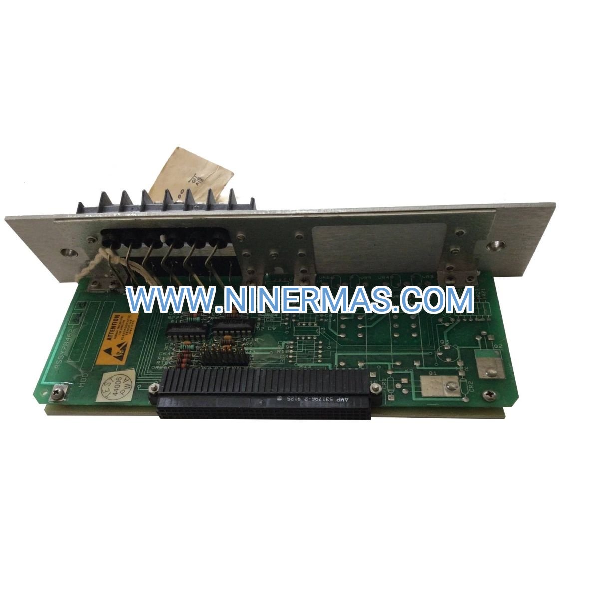
The 84157-01 is a precision-engineered signal relay board designed for continuous machinery vibration monitoring in industrial environments. Manufactured by Bently Nevada as part of the 3300 Series platform, this module transforms raw seismic sensor data into actionable alarm signals and standardized analog outputs. It serves as the critical interface between field-mounted transducers and plant control systems, enabling automated protection strategies that prevent catastrophic equipment failures while minimizing false trips.
Engineered for reliability in harsh industrial settings, the 84157-01 addresses the fundamental challenge of converting low-level vibration signals into reliable protection logic. Plant engineers deploy this module to safeguard rotating equipment—motors, pumps, fans, compressors—where bearing wear, imbalance, or misalignment manifests as elevated vibration. The dual-stage alarm architecture provides graduated response capability: early-warning alerts enable predictive maintenance intervention, while danger-level trips execute automatic shutdown sequences that protect personnel and assets.
Target users include maintenance engineers managing critical rotating assets, instrumentation technicians implementing vibration monitoring systems, and reliability professionals developing condition-based maintenance programs. The module's compatibility with industry-standard velocity transducers and accelerometers, combined with flexible relay outputs and analog signal options, makes it suitable for retrofit installations on legacy equipment and new-build projects requiring integrated machinery protection.
Core Features & Business Value
→ Dual-Channel Signal Processing: Accepts velocity (10-1000 Hz) and acceleration (1-10 kHz) inputs from seismic sensors, enabling comprehensive vibration spectrum coverage from low-speed bearing defects to high-frequency gear mesh anomalies. Business value: Single module handles diverse machinery types, reducing spare parts inventory and simplifying technician training.
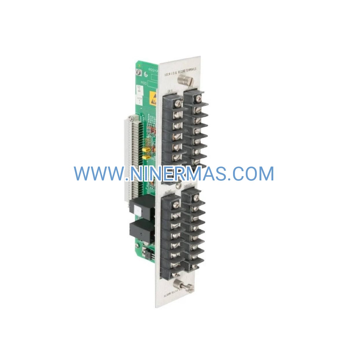
→ Two-Stage Alarm Logic: Independent Alert and Danger setpoints with dedicated relay outputs (Form C, 5A @ 250 VAC) enable graduated response strategies. Business value: Balances equipment protection with operational continuity—avoid nuisance trips while ensuring fail-safe shutdown when vibration indicates imminent failure.
→ Integrated Signal Conditioning: Onboard amplification, bandpass filtering, and integration circuits optimize signal quality before alarm comparison. Business value: Eliminates external signal conditioners, reducing installation costs and panel space requirements by 40-60%.
→ Standardized Analog Output: Configurable 4-20mA or ±10 VDC output feeds DCS systems, PLCs, or chart recorders for trending and remote monitoring. Business value: Enables centralized condition monitoring without dedicated vibration analyzers—leverage existing control infrastructure.
✓ Electrical Isolation: Relay contacts electrically isolated from signal circuits prevent ground loops and protect sensitive electronics from control circuit transients. Business value: Reduces troubleshooting time and eliminates intermittent failures caused by electrical noise.
✓ Universal Power Input: Accepts 24 VDC or 115/230 VAC, simplifying integration into diverse plant electrical systems. Business value: Single part number serves global installations, reducing procurement complexity and lead times.
Application Scenarios
Scenario 1: Critical Motor Protection in Water Treatment Plants
Municipal water facilities operate large circulation pumps and blowers continuously—unplanned downtime disrupts service and triggers regulatory violations. Install velocity transducers on motor bearing housings, feeding signals to the 84157-01. Configure Alert at 0.3 in/sec (triggers maintenance notification) and Danger at 0.5 in/sec (initiates automatic motor shutdown). Value delivered: Prevents catastrophic bearing failures that cause 3-7 day outages; enables scheduled maintenance during low-demand periods, reducing emergency repair costs by 70-80%.
Scenario 2: Fan Imbalance Detection in HVAC Systems
Commercial HVAC systems use large centrifugal fans where blade fouling or bearing wear causes imbalance and elevated vibration. Mount accelerometers on fan housings to capture high-frequency blade pass signatures. The 84157-01 processes acceleration signals, triggering alarms when vibration exceeds 2.0g (Alert) or 3.5g (Danger). Value delivered: Early detection of imbalance prevents blade liberation events that damage ductwork and create safety hazards; reduces unscheduled downtime by 60%.
Scenario 3: Pump Cavitation Monitoring in Chemical Processing
Centrifugal pumps handling corrosive chemicals experience cavitation when suction pressure drops—cavitation causes rapid impeller erosion and seal failures. Deploy velocity transducers to detect the characteristic high-frequency vibration signature of cavitation. The relay board's bandpass filtering isolates cavitation frequencies (500-1000 Hz) from normal pump vibration. Value delivered: Prevents impeller replacement costs ($5,000-$15,000) and unplanned process shutdowns; extends pump MTBF from 18 months to 36+ months.
Scenario 4: Gearbox Bearing Surveillance in Material Handling
Conveyor drive gearboxes in mining and aggregate operations operate in high-dust environments where bearing contamination accelerates wear. Install accelerometers on gearbox housings to monitor bearing defect frequencies (typically 3-8 kHz). The 84157-01's high-frequency response captures early-stage bearing damage signatures invisible to velocity measurements. Value delivered: Provides 4-8 week advance warning of bearing failures, enabling planned replacements during scheduled maintenance windows; reduces gearbox rebuild costs by 50%.
Scenario 5: Compressor Protection in Refrigeration Systems
Industrial refrigeration compressors require continuous operation—vibration from worn bearings or valve failures threatens product loss in cold storage facilities. Mount velocity transducers on compressor bodies, connecting to the 84157-01 for 24/7 monitoring. Relay outputs integrate with refrigeration control panels, triggering backup compressor startup when primary unit vibration exceeds Alert thresholds. Value delivered: Prevents product spoilage events ($50,000-$200,000 losses); maintains cold chain integrity during equipment transitions.
Technical Parameters & Selection Guide
| Parameter | Specification | Notes |
|---|---|---|
| Part Number | 84157-01 | Factory-sealed, current production |
| Input Signal Types | Velocity, Acceleration | Dual-channel capability |
| Velocity Range | 10-1000 Hz | Optimized for motors, pumps, fans |
| Acceleration Range | 1-10,000 Hz | High-speed machinery, gearboxes |
| Sensor Compatibility | 100 mV/in/sec (velocity), 100 mV/g (accel) | Industry-standard sensitivities |
| Relay Outputs | Form C (SPDT), 5A @ 250 VAC / 30 VDC | Alert + Danger stages |
| Analog Output | 4-20mA or ±10 VDC (configurable) | For DCS/PLC integration |
| Power Input | 24 VDC or 115/230 VAC | Universal compatibility |
| Operating Temperature | -20°C to +65°C | Industrial-grade rating |
| Mounting Options | DIN rail, panel mount | Includes hardware |
| Certifications | UL, CE, CSA | Global compliance |
Selection Criteria: Choose velocity input mode for machinery operating below 3600 RPM (motors, pumps, fans) where bearing defects and imbalance generate vibration in the 10-1000 Hz range. Select acceleration input mode for high-speed equipment (turbines, compressors, gearboxes above 3600 RPM) where critical frequencies exceed 1 kHz. For installations requiring both low-frequency and high-frequency monitoring, deploy two modules or use the acceleration input with integration to derive velocity.
Alarm Setpoint Recommendations: Set Alert thresholds at 50-70% of equipment manufacturer's trip limits to provide adequate warning time. For motors and pumps, typical Alert values are 0.3 in/sec (velocity) or 1.5g (acceleration); Danger values are 0.5 in/sec or 3.0g. Adjust setpoints based on baseline vibration measurements taken during commissioning—set Alert at 2× baseline, Danger at 3-4× baseline.
Extended Functions
Remote Monitoring Integration: The 4-20mA analog output enables integration with SCADA systems, cloud-based condition monitoring platforms, and mobile alert applications. Connect the output to IIoT gateways for real-time vibration trending accessible via web dashboards or smartphone apps—maintenance teams monitor equipment health remotely, reducing site visits by 40-60%.
Multi-Point Monitoring Networks: Deploy multiple 84157-01 modules in distributed architectures where a single PLC or DCS collects alarm signals from dozens of machines. Use the relay outputs as discrete inputs to the control system, creating centralized alarm annunciation and automated response logic. This approach suits facilities with 20+ critical machines requiring coordinated protection strategies.
Customization Options: Factory configuration services available for high-volume orders—specify custom alarm setpoints, output scaling, and relay logic programmed at the factory. Reduces commissioning time by 50-70% for large installations with standardized equipment types.
Delivery & Service Assurance
Lead Time: Standard stock items ship within 1-3 business days via express courier (DHL, FedEx, UPS). Custom-configured modules require 2-3 weeks for factory programming and testing. Expedited processing available for emergency replacements—contact our technical sales team for same-day shipping options.
Warranty Coverage: 12-month manufacturer warranty covers defects in materials and workmanship. Warranty includes free replacement or repair, with advance replacement available to minimize downtime. Extended warranty programs (24-36 months) available for critical applications.
Technical Support: Lifetime technical support included—our application engineers assist with sensor selection, wiring diagrams, alarm setpoint calculations, and troubleshooting. Support available via email (response within 4 hours), phone (8 AM - 6 PM CST, Monday-Friday), and remote diagnostics for complex issues.
Documentation Package: Each module ships with installation manual, wiring diagrams, sensor compatibility matrices, alarm setpoint worksheets, and calibration certificates. Digital documentation library includes CAD drawings (DWG, PDF), 3D models (STEP), and PLC integration examples for common platforms (Allen-Bradley, Siemens, Modicon).
Frequently Asked Questions
Q1: Can the 84157-01 relay board interface with wireless vibration sensors for remote machinery monitoring?
A: The module accepts hardwired sensor inputs only—wireless sensors require separate receivers that output analog signals compatible with the 84157-01 inputs. For wireless deployments, use wireless sensor systems with 4-20mA or ±10 VDC outputs, connecting these to the relay board's analog input terminals. This configuration enables wireless sensor flexibility while leveraging the module's alarm relay and signal conditioning capabilities.
Q2: What is the maximum cable length between seismic sensors and the relay board without signal degradation?
A: Maximum recommended cable length is 300 meters (1000 feet) using shielded twisted-pair cable with capacitance ≤100 pF/meter. Longer cable runs introduce capacitive loading that attenuates high-frequency signals and increases noise susceptibility. For installations exceeding 300 meters, use sensor-mounted preamplifiers or 4-20mA transmitters that provide low-impedance outputs immune to cable length effects.
Q3: How much energy savings can vibration monitoring deliver in motor-driven systems?
A: Vibration monitoring enables condition-based maintenance that reduces energy consumption by 8-15% compared to run-to-failure strategies. Early detection of bearing wear, misalignment, and imbalance allows corrective action before these conditions increase friction losses and motor current draw. Additionally, preventing catastrophic failures avoids emergency repairs that often result in oversized replacement motors operating inefficiently at partial load.
Q4: What are the installation requirements for mounting the relay board in hazardous area applications?
A: The standard 84157-01 is rated for general industrial environments (non-hazardous). For Class I Division 2 or ATEX Zone 2 installations, mount the module in a purged enclosure or use intrinsically safe barriers on sensor input circuits. Bently Nevada offers explosion-proof variants (consult factory for part numbers) certified for Class I Division 1 / Zone 1 applications where the module must be installed within the hazardous area.
Q5: Can the module's alarm setpoints be adjusted remotely via Modbus or Ethernet protocols?
A: The 84157-01 uses local potentiometer or DIP switch configuration—remote setpoint adjustment requires upgrading to Bently Nevada's 3500 Series rack-based monitors with Ethernet connectivity. For applications requiring remote configuration, consider the 3500/42M Proximitor monitor with Modbus TCP capability, which provides equivalent functionality with network-based setpoint management.
Q6: What is the typical response time from vibration event to relay activation for emergency shutdown applications?
A: Relay activation occurs within 50-100 milliseconds of the vibration signal exceeding the configured threshold. This response time includes signal conditioning, threshold comparison, and relay coil energization. For applications requiring faster response (e.g., high-speed turbines), use dedicated proximity probe systems with <10 ms response times designed for emergency overspeed protection.
Take the Next Step
Protect your critical rotating assets with proven vibration monitoring technology. The 84157-01 relay board delivers industrial-grade reliability, flexible integration options, and the performance you need to prevent costly equipment failures. Our technical team is ready to assist with sensor selection, system design, and application-specific configuration.
Request a quote today: Contact our sales engineers at sale@ninermas.com or call +0086 187 5021 5667. Provide your machinery specifications, vibration monitoring objectives, and installation timeline—we'll deliver a customized solution with competitive pricing and fast delivery.
Need technical guidance? Download our free Vibration Monitoring Selection Guide (PDF) or schedule a 30-minute consultation with our application engineers. We'll help you design a monitoring strategy that maximizes equipment uptime while minimizing false alarms and installation costs.
© 2026 NINERMAS COMPANY LIMITED. All rights reserved.
Original Source: https://ninermas.com
Contact: sale@ninermas.com | +0086 187 5021 5667

Contact Info
-
Address:22 / F, South Wo Hang building, 148 Wing Lok Street, Sheung Wan, Western District, Hong Kong
-
Phone:+8618750215667
-
Email: