Bently Nevada 72937-01 Valve Positioner Indicator | SIL 2 ESD Control Module | Industrial Automation
Description
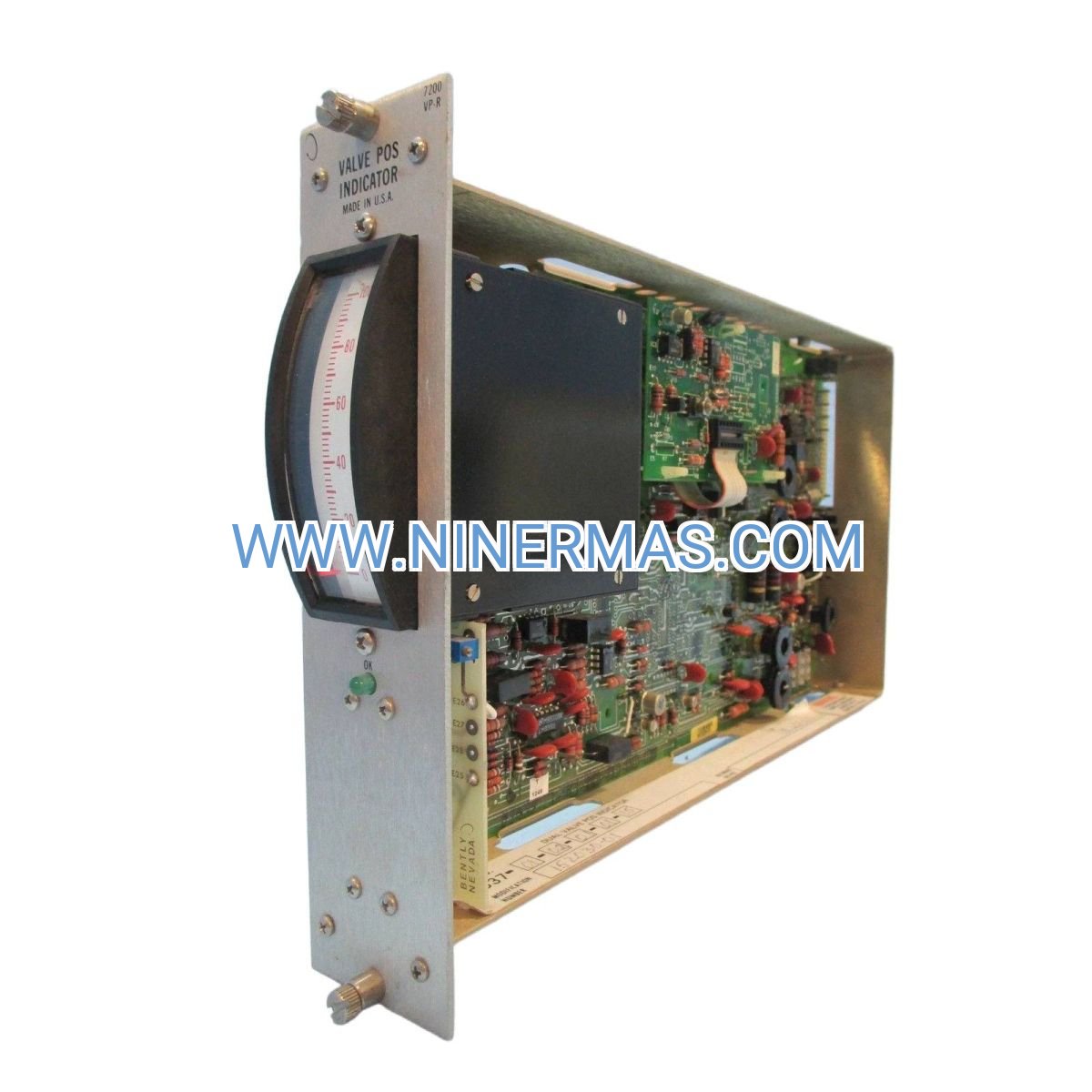
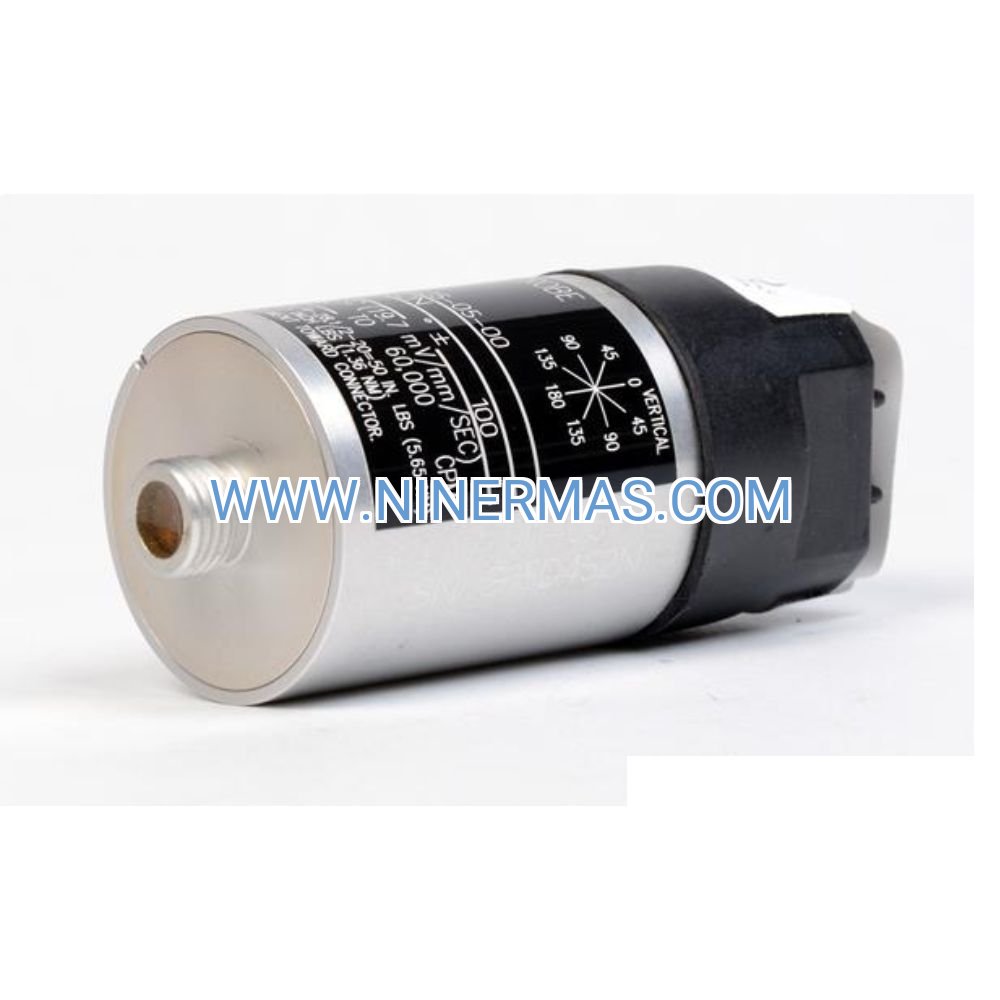
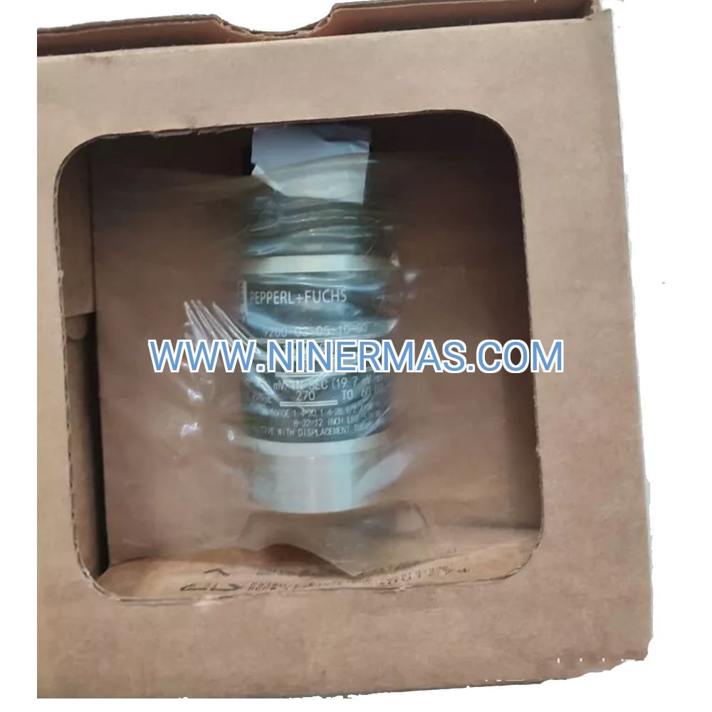
Bently Nevada 72937-01 Valve Positioner Indicator (Industrial-Grade Safety Control Module)
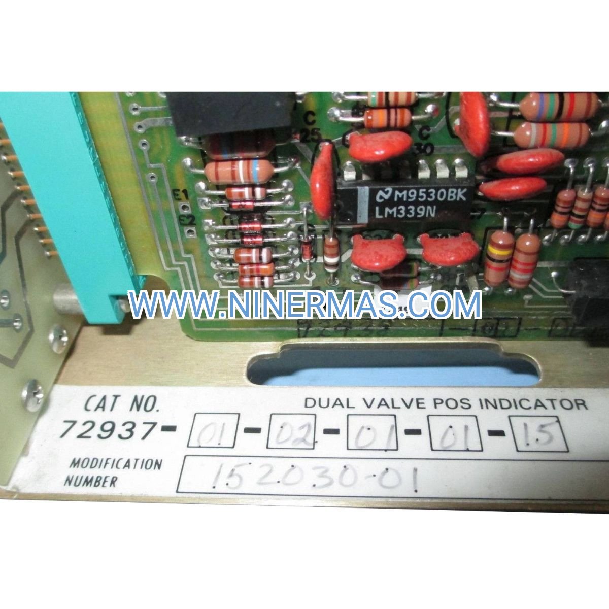
The Bently Nevada 72937-01-02-01-01-15 Valve Positioner Indicator is a precision industrial control device designed for real-time valve position monitoring and feedback in critical safety and process control applications. Through advanced analog signal processing (4-20mA/LVDT input) and dual-protocol communication (Modbus RTU/HART), this module delivers accurate valve position data with ±0.5% precision, ensuring reliable operation in Emergency Shutdown (ESD) systems, process control valves, and automated actuation systems.
Engineered for high-stakes industrial environments including oil & gas facilities, petrochemical plants, power generation stations, and water treatment systems, this module addresses common challenges such as valve position uncertainty, delayed fault detection, inadequate safety integrity levels, and limited remote diagnostic capabilities. The SIL 2 certification ensures compliance with IEC 61508 functional safety standards, making it ideal for safety-instrumented systems.
With standardized design and flexible configuration options, the 72937-01 module offers exceptional reliability, seamless integration with existing DCS/PLC systems, comprehensive diagnostic capabilities, and simplified maintenance protocols. Suitable for design engineers, system integrators, EPC contractors, and plant maintenance teams. Contact our application engineers for customized configuration guidance and technical quotations.
Core Functions & Advantages
- Precision Position Feedback
Accepts 4-20mA analog or LVDT displacement signals from valve actuators, converting physical position into digital data with ±0.5% linearity accuracy. Eliminates guesswork in valve status verification and reduces process variability. - Dual-Protocol Communication
Supports both Modbus RTU (RS-485) and HART protocol for seamless integration with modern DCS, SCADA, and asset management systems. Enables real-time position monitoring and remote diagnostics without additional gateways. - SIL 2 Safety Certification
Certified to IEC 61508 SIL 2 standards, providing proven reliability for safety-instrumented functions in Emergency Shutdown (ESD) and High Integrity Pressure Protection Systems (HIPPS). Reduces risk of spurious trips and dangerous failures. - Comprehensive Diagnostic Features
Built-in self-diagnostics continuously monitor signal integrity, power supply status, and communication health. Early fault detection minimizes unplanned downtime and supports predictive maintenance strategies. - Rugged Industrial Construction
Designed for harsh environments with wide operating temperature range (-40°C to +85°C), EMI/RFI immunity, and conformal coating protection. Suitable for hazardous area installations when properly certified enclosures are used. - Flexible Configuration Options
Field-configurable input ranges, output scaling, damping parameters, and alarm thresholds via HART communicator or Modbus interface. Adapts to various valve types and actuator specifications without hardware changes.
Typical Application Scenarios
This valve positioner indicator is specifically designed for applications requiring high reliability, accurate position feedback, and safety integrity. Key deployment scenarios include:
- Emergency Shutdown (ESD) Systems
Provides critical position verification for ESD valves in oil & gas production facilities, offshore platforms, and refinery units. Ensures valves reach safe positions during emergency events, meeting API 14C and IEC 61511 requirements. - Process Control Valve Monitoring
Monitors control valve position in continuous process industries including chemical manufacturing, pharmaceutical production, and food processing. Enables closed-loop control optimization and reduces process deviation. - High Integrity Pressure Protection (HIPPS)
Serves as final element position feedback in HIPPS applications, preventing overpressure scenarios in pipelines and pressure vessels. Supports SIL 2/3 loop integrity when combined with appropriate logic solvers. - Steam & Power Generation Systems
Tracks turbine control valve, bypass valve, and isolation valve positions in power plants and cogeneration facilities. Improves turbine protection and optimizes thermal efficiency through precise valve control. - Water & Wastewater Treatment
Monitors actuated valves in municipal water distribution, wastewater treatment plants, and industrial water recycling systems. Ensures proper flow control and supports automated process sequences.
Technical Parameters & Selection Guide
To facilitate engineering design and product selection, we provide standardized technical specifications. Custom configurations are available based on project-specific requirements.
| Parameter | Specification |
|---|---|
| Model Number | 72937-01-02-01-01-15 |
| Input Signal Type | 4-20mA DC / LVDT (configurable) |
| Input Accuracy | ±0.5% of span (typical) |
| Communication Protocols | Modbus RTU (RS-485), HART (overlay on 4-20mA) |
| Power Supply | 24 VDC ±20% (typical) |
| Power Consumption | < 5W (typical) |
| Operating Temperature | -40°C to +85°C (-40°F to +185°F) |
| Storage Temperature | -50°C to +90°C (-58°F to +194°F) |
| Humidity Range | 5% to 95% RH (non-condensing) |
| Safety Certification | SIL 2 capable per IEC 61508 |
| Enclosure Rating | Suitable for IP20 minimum (depends on installation) |
| Mounting | DIN rail or panel mount (adapter required) |
| Dimensions (H×W×D) | Approximately 120mm × 80mm × 60mm |
| Weight | 0.2 kg (0.44 lbs) |
Selection Recommendations:
When selecting this module, consider the following factors: valve actuator signal type (4-20mA vs. LVDT), required communication protocol (Modbus/HART/both), power supply availability (24 VDC standard), environmental conditions (temperature/humidity/vibration), safety integrity level requirements (SIL 1/2/3), and available panel/DIN rail mounting space. For assistance with configuration and integration, please provide your application details including valve type, actuator specifications, control system interface requirements, and environmental conditions. Our application engineers will recommend the optimal configuration and provide integration support documentation.
Advanced Integration Capabilities
- DCS/SCADA Integration
Native Modbus RTU support enables direct connection to Honeywell, Emerson DeltaV, Siemens PCS 7, Yokogawa Centum, and ABB System 800xA platforms. Pre-configured function blocks and device descriptions available for rapid commissioning. - Asset Management Systems
HART protocol compatibility allows integration with AMS Device Manager, Pactware, and other FDT/DTM-based asset management tools. Supports remote configuration, calibration verification, and predictive diagnostics without process interruption. - Safety System Integration
Certified for use in SIL 2 safety loops when combined with appropriate safety PLCs (Triconex, Siemens Safety Integrated, Allen-Bradley GuardLogix). Detailed safety manual and proof test procedures provided for compliance documentation. - Redundancy & Fault Tolerance
Supports dual-channel configurations for critical applications requiring 1oo2 or 2oo3 voting architectures. Diagnostic coverage exceeds 90% for systematic fault detection, meeting IEC 61508 requirements for SIL 2 hardware fault tolerance.
Delivery, Service & Quality Assurance
Lead Time: Standard catalog items typically ship within 3-5 business days from stock. Custom-configured modules require 2-3 weeks for factory programming and testing. Expedited service available for urgent projects.
Warranty: All modules include a minimum 12-month manufacturer's warranty covering defects in materials and workmanship. Extended warranty options available for critical applications.
Technical Support: Comprehensive technical support includes remote configuration assistance, integration troubleshooting, and on-site commissioning services (subject to location and project scope). Our engineering team provides application notes, wiring diagrams, and Modbus/HART register maps.
Documentation Package: Each module ships with complete technical documentation including installation manual, electrical connection diagrams, Modbus register mapping, HART DD file, SIL certification documents, and proof test procedures. CAD drawings and 3D models available upon request for panel design.
Quality Certifications: Manufactured under ISO 9001:2015 quality management system. SIL 2 certification per IEC 61508. RoHS compliant. CE marked for European markets. Additional certifications (ATEX, IECEx, FM, CSA) available for hazardous area applications when installed in approved enclosures.
Frequently Asked Questions (FAQ)
Q: How does the Bently Nevada 72937-01 valve positioner indicator integrate with existing control systems?
A: The module supports both Modbus RTU (RS-485) and HART protocols, enabling direct connection to most modern DCS, PLC, and SCADA systems. For Modbus integration, connect via RS-485 terminals and configure the appropriate slave address (1-247). For HART integration, the protocol overlays on the 4-20mA signal using a HART modem or multiplexer. Detailed register maps and device description files are provided for seamless configuration.
Q: What is the maximum number of valve positioners that can be connected on a single Modbus network?
A: A single Modbus RTU network supports up to 247 addressable devices (slave addresses 1-247). Practical limitations depend on network topology, cable length (up to 1200m with proper termination), baud rate (typically 9600-115200 bps), and polling cycle requirements. For large installations, we recommend segmenting networks or using Modbus TCP gateways for improved performance.
Q: What level of energy savings or performance improvement can be expected?
A: While the module itself is a monitoring device (not a controller), accurate position feedback enables optimized valve control strategies that can reduce process variability by 15-30%, minimize valve wear through reduced hunting/oscillation, and prevent energy waste from partially-open isolation valves. In ESD applications, verified valve position reduces spurious trips and associated production losses, which can exceed $100,000 per incident in process industries.
Q: What are the environmental requirements for installation? What is the ingress protection rating?
A: The module operates reliably in -40°C to +85°C ambient temperature with 5-95% relative humidity (non-condensing). The electronics module itself is designed for IP20 minimum protection (suitable for control panel mounting). For outdoor or harsh environment installations, mount the module inside a NEMA 4X/IP65 or higher rated enclosure with appropriate climate control. Conformal coating provides additional protection against moisture and contaminants.
Q: Does the module support remote monitoring and data acquisition? Which protocols are compatible?
A: Yes, the module fully supports remote monitoring via Modbus RTU and HART protocols. Modbus provides real-time position data, alarm status, and diagnostic information accessible by SCADA systems, historians (OSIsoft PI, Honeywell PHD), and cloud platforms via Modbus-to-Ethernet gateways. HART protocol enables advanced diagnostics, configuration, and calibration data access through asset management systems. OPC UA connectivity is achievable through third-party protocol converters.
Q: Is the module suitable for SIL 3 safety applications?
A: The 72937-01 is certified for SIL 2 capability per IEC 61508. For SIL 3 applications, the module can be used in redundant configurations (1oo2D or 2oo3 voting) with appropriate safety logic solvers. Detailed safety manual, FMEDA report, and proof test procedures are available to support safety lifecycle documentation per IEC 61511. Consult our safety engineers for SIL 3 architecture design guidance.
Q: What calibration and maintenance procedures are required?
A: The module requires periodic proof testing per IEC 61511 requirements (typically 12-24 month intervals for SIL 2 applications). Calibration verification can be performed using HART communicator or Modbus commands without removing the module from service. Recommended maintenance includes visual inspection of connections, verification of communication integrity, and functional testing of alarm outputs. Detailed proof test procedures and calibration certificates are provided with each unit.
Request Technical Support & Quotation
To receive detailed application engineering support, customized configuration recommendations, or project quotations, please provide the following information to our technical team:
- Project name and application overview
- Valve type and actuator specifications (manufacturer, model, signal type)
- Required communication protocol (Modbus RTU, HART, or both)
- Control system interface requirements (DCS/PLC model, I/O specifications)
- Quantity required and delivery timeline
- Environmental conditions (temperature range, hazardous area classification if applicable)
- Safety integrity level requirements (SIL 1/2/3)
Our application engineers will provide one-on-one consultation, configuration guidance, integration support documentation, and competitive pricing within 24-48 hours.
© 2026 NINERMAS COMPANY LIMITED. All rights reserved.
Original Source: https://ninermas.com
Contact: sale@ninermas.com | +0086 187 5021 5667

Contact Info
-
Address:22 / F, South Wo Hang building, 148 Wing Lok Street, Sheung Wan, Western District, Hong Kong
-
Phone:+8618750215667
-
Email: