
Description
Industrial-Grade Position Monitor for Critical Turbomachinery Applications
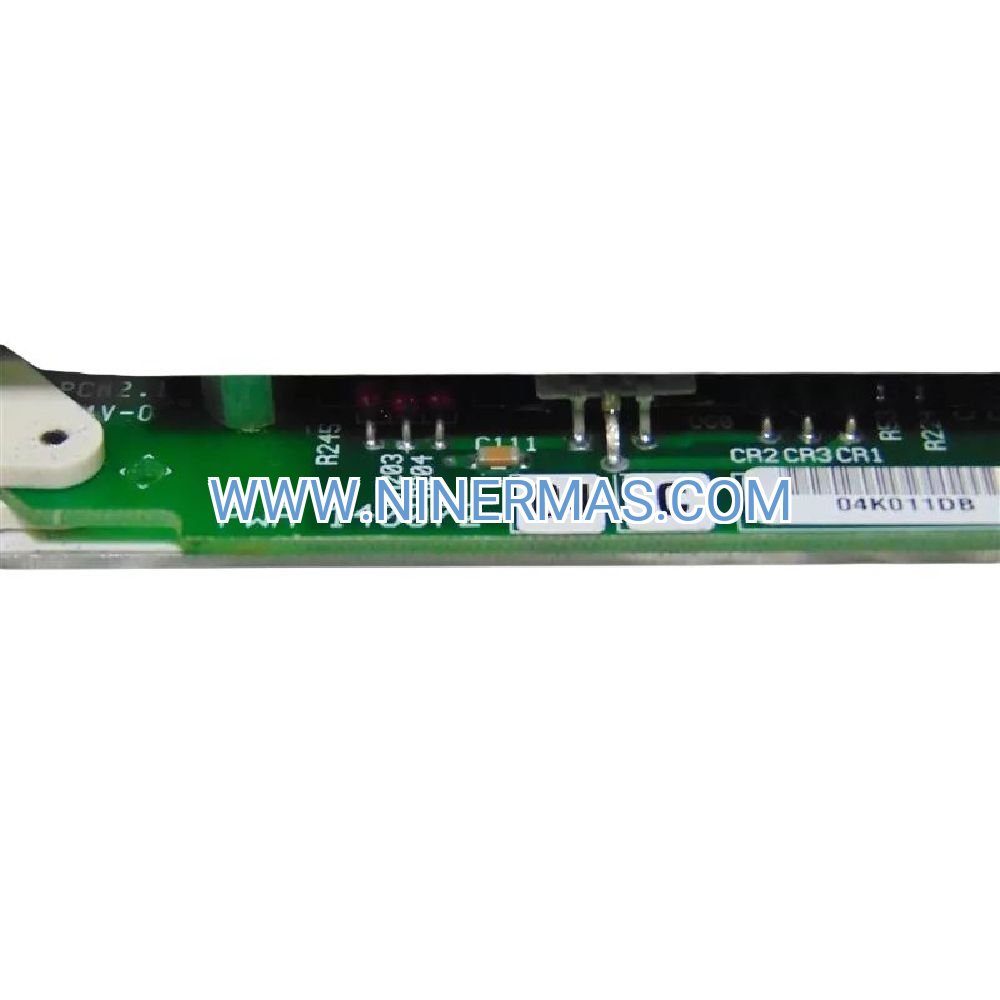
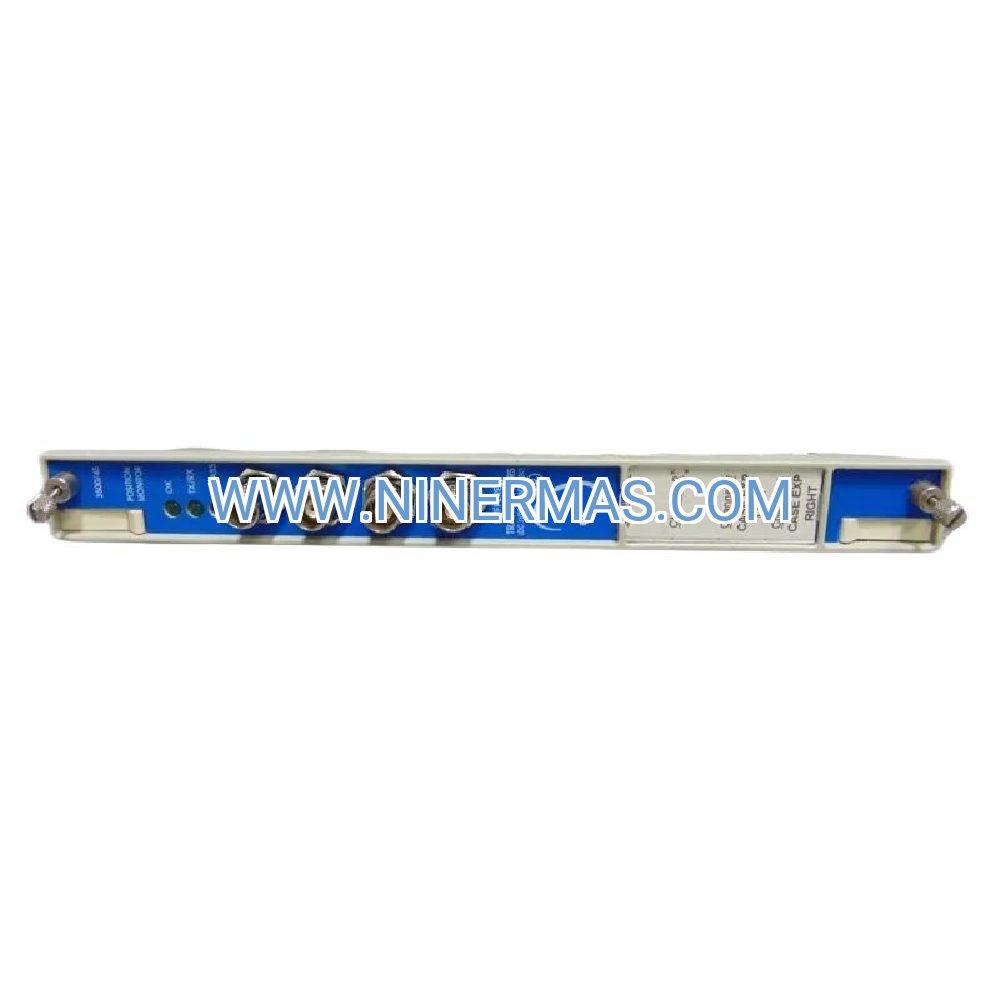
Engineered for high-stakes industrial environments, the Bently Nevada 3500/45 (Model 140072-04C) delivers precision axial displacement monitoring across four independent channels. This rack-mounted protection module interfaces with proximity transducers and LVDTs to safeguard rotating equipment against thrust bearing failures, thermal expansion anomalies, and valve positioning errors in power generation, oil & gas, and process industries.
Designed to meet API 670 machinery protection standards, this module provides continuous surveillance of thrust position, differential expansion, and linear displacement parameters critical to preventing catastrophic turbomachinery failures. Each channel operates independently with dedicated alarm logic, enabling simultaneous monitoring of multiple measurement points within a single compact module.
Whether protecting steam turbines from rotor-to-stator contact, monitoring gas turbine thermal growth, or tracking compressor magnetic bearing position, the 3500/45 combines measurement precision with industrial-grade reliability to minimize unplanned downtime and extend equipment service life.
Core Capabilities & Performance Advantages
The 3500/45 position monitor transforms raw transducer signals into actionable protection intelligence:
- → Quad-Channel Architecture: Monitor four independent position parameters simultaneously—thrust bearing clearance, casing expansion, valve stem travel, and rotor float—consolidating measurements that traditionally required multiple modules and reducing rack space consumption by 75%.
- → High-Resolution Measurement: 16-bit analog-to-digital conversion delivers 0.0015% full-scale resolution, enabling detection of axial displacement changes as small as 0.001 inches (25 microns) for early identification of bearing wear, thermal distortion, and mechanical degradation.
- → Universal Transducer Compatibility: Accepts DC voltage inputs from -24V to +24V, interfacing seamlessly with Bently Nevada 3300 XL proximity systems, 7200 Series eddy current probes, and third-party LVDTs without signal conditioning requirements.
- → Differential Calculation Engine: Automatically computes differential expansion by subtracting paired proximity probe signals, compensating for thermal case growth and providing true rotor-to-stator clearance measurement critical for turbine startup sequencing.
- → Dual-Setpoint Alarm Logic: Each channel supports independent Alert and Danger thresholds with configurable hysteresis and time delays, implementing two-stage protection that warns operators before initiating emergency shutdowns.
- ✓ Rate-of-Change Detection: Monitors velocity of position changes to identify rapid thrust shifts indicating imminent bearing failure, coupling problems, or rotor rubs—conditions that develop too quickly for absolute position alarms alone.
Mission-Critical Application Scenarios
The 3500/45 module addresses specific turbomachinery protection challenges across diverse industries:
Steam Turbine Generator Protection: In 3600 RPM turbine-generators producing 50-500 MW, the module tracks thrust bearing position during load ramping and startup/shutdown cycles. When steam admission valves open unevenly or condenser vacuum fluctuates, axial thrust forces can shift the rotor by several millimeters within seconds. The 3500/45 detects these movements before metal-to-metal contact occurs, preventing journal bearing damage and rotor-to-stator rubs that cause multi-million dollar repairs and months of forced outage.
Gas Turbine Thermal Expansion Monitoring: Aero-derivative and heavy-duty gas turbines experience significant differential expansion between the hot rotor and cooler casing during rapid load changes. The module measures this expansion using paired proximity probes at the turbine and compressor ends, verifying that clearances remain within safe limits. Excessive differential expansion triggers load reduction or shutdown before blade tips contact the casing, preventing catastrophic compressor surge and hot section damage.
Centrifugal Compressor Magnetic Bearing Supervision: In oil-free compressors using active magnetic bearings for corrosive or high-purity gas service, the 3500/45 monitors radial bearing position as a backup protection layer. If magnetic bearing controllers fail or lose power, the module detects rotor touchdown onto mechanical backup bearings and initiates controlled shutdown, preventing bearing seizure and impeller-to-diffuser contact in equipment where repairs exceed $2 million.
Hydroelectric Wicket Gate Position Verification: Large hydro turbines rely on wicket gate position for load control and overspeed protection. The module monitors LVDT signals from gate actuators, comparing commanded versus actual position. Discrepancies indicate mechanical binding, hydraulic system failures, or governor malfunctions that could lead to runaway overspeed conditions, providing independent verification beyond the turbine control system.
Cryogenic Expander Clearance Control: LNG liquefaction plants and air separation units operate turbo-expanders at temperatures below -160°C. Extreme thermal contraction creates dynamic clearance changes between rotating and stationary components. The 3500/45 tracks differential expansion throughout cooldown and warmup cycles, preventing seal damage and ensuring efficient operation across the full temperature range.
Technical Specifications & Measurement Parameters
| Catalog Number | 140072-04C |
| Product Series | 3500 Rack Configuration System |
| Measurement Channels | 4 independent position inputs |
| Input Signal Type | DC voltage from proximity transducers or LVDTs |
| Input Voltage Range | -24 VDC to +24 VDC |
| Configurable Span | ±500 mils (±12.7 mm) typical, user-scalable |
| Measurement Accuracy | ±0.5% of full scale (includes linearity, hysteresis, repeatability) |
| A/D Resolution | 16-bit conversion (0.0015% FS) |
| Sampling Rate | 1000 samples/second per channel |
| Alarm Outputs | 4 relay outputs (1 per channel), configurable logic |
| Relay Contact Rating | 5A @ 30 VDC or 250 VAC resistive |
| Communication Protocol | Proprietary 3500 backplane interface |
| Power Requirement | 7.5W from rack power supply |
| Operating Temperature | -30°C to +65°C (-22°F to +149°F) |
| Humidity Tolerance | 5% to 95% RH non-condensing |
| Physical Dimensions | 24.4 × 241.8 × 241.3 mm (0.96" × 9.52" × 9.50") |
| Module Weight | 0.91 kg (2.0 lbs) |
| Rack Compatibility | Any slot in 3500/05 system rack |
Advanced Protection Features & Diagnostic Intelligence
Beyond basic position measurement, the 3500/45 incorporates sophisticated protection algorithms:
Voting Logic Implementation: Supports 2-out-of-3 voting configurations for critical shutdown applications, reducing nuisance trips while maintaining SIL-rated safety integrity. When three channels monitor the same parameter, two must exceed alarm thresholds before initiating protective action, filtering transient spikes and sensor anomalies.
Transducer Health Monitoring: Continuously verifies proximitor power supply voltage and detects open circuits, short circuits, and cable faults. When sensor problems occur, the module annunciates specific fault codes rather than generating false position alarms, accelerating troubleshooting and preventing unnecessary equipment shutdowns.
Configurable Engineering Units: Accepts user-defined scaling in mils, millimeters, inches, or percentage of full scale. Supports both linear and polynomial scaling functions to accommodate non-linear LVDT characteristics, ensuring accurate measurement across the full transducer range.
Gap Voltage Display: Provides real-time visibility into raw proximitor gap voltage for each channel, enabling technicians to verify sensor installation, detect target surface contamination, and diagnose intermittent wiring issues without external test equipment.
Event Capture & Timestamping: Records alarm events with precise timestamps, peak values, and duration for post-trip forensic analysis. Event logs support regulatory compliance documentation and root cause investigation of machinery failures.
System Architecture & Integration Requirements
The 3500/45 module operates within the comprehensive 3500 monitoring ecosystem:
Rack Installation: Mounts in any available slot of a 3500/05 instrument rack (2-slot through 17-slot configurations). Does not require specific slot positioning, allowing flexible system layout based on cable routing and I/O requirements.
I/O Module Pairing: Requires companion 3500/45 I/O module (part number 135137-01 or 135145-01) installed in the rear of the rack. The I/O module provides screw terminal connections for relay outputs and recorder outputs, isolating field wiring from the monitor electronics.
Configuration Software: Programmed using 3500 Rack Configuration Software, a Windows-based application that provides graphical setup of channel scaling, alarm setpoints, relay logic, and diagnostic parameters. Configuration files can be saved, versioned, and uploaded to multiple racks for standardization.
Communication Gateway Integration: Interfaces with 3500/92 Communication Gateway module to provide Modbus TCP/IP connectivity for DCS and SCADA integration. Position values, alarm status, and diagnostic data stream to plant control systems for centralized monitoring and historian archiving.
Transient Data Acquisition: Works in conjunction with 3500/22M Transient Data Interface to capture high-resolution position waveforms during alarm events. Waveform data uploads to System 1 condition monitoring software for detailed analysis of thrust bearing behavior and thermal expansion patterns.
Installation Best Practices & Commissioning Procedures
Proper installation ensures measurement accuracy and long-term reliability:
Transducer Selection: Use Bently Nevada 3300 XL 8mm or 11mm proximity systems with -24 VDC output for thrust and expansion measurements. For valve position and linear displacement, specify LVDTs with ±10 VDC output and appropriate stroke length.
Cable Routing Discipline: Route position sensor cables in dedicated cable trays separated from AC power, VFD cables, and high-current circuits. Use shielded twisted-pair cable for runs exceeding 50 meters to minimize electromagnetic interference. Maintain minimum 300mm separation from power cables.
Grounding Strategy: Connect cable shields to ground at the proximitor end only using the shield grounding terminal. Verify ground resistance below 1 ohm to prevent ground loops. Never ground shields at both ends, as this creates circulating currents that introduce measurement noise.
Scaling Calibration: Perform two-point calibration using precision gap gauges (for proximity probes) or LVDT simulators (for linear transducers). Verify that displayed position matches physical displacement within ±0.5% across the full measurement range. Document calibration results for future reference.
Alarm Verification Testing: Simulate alarm conditions using calibration tools to verify setpoint accuracy, relay operation, and DCS integration. Confirm that Alert alarms annunciate without initiating shutdown, while Danger alarms trigger appropriate protective actions. Test bypass functionality and verify that bypassed channels do not affect voting logic.
Diagnostic Capabilities & Troubleshooting Guide
The module provides comprehensive diagnostic feedback for rapid fault isolation:
LED Status Indicators: Four green channel LEDs confirm normal operation; red LEDs indicate alarm conditions. Amber OK LED verifies module power, backplane communication, and passing self-diagnostics. Yellow Bypass LED shows when channels are bypassed for maintenance.
Common Issues & Resolutions:
- Erratic Position Readings: Check proximity probe gap (should be 40-60 mils), inspect cable connections for corrosion, verify target surface is clean and free of debris.
- Alarm Chatter: Increase hysteresis setting or add time delay to filter process noise and vibration-induced position fluctuations.
- No Relay Output: Verify I/O module installation, check relay wiring at terminal blocks, confirm relay logic configuration in software.
- Calibration Drift: Inspect transducer for contamination, verify proximitor power supply voltage, check for cable damage or moisture ingress.
Predictive Maintenance Applications
Position trending enables early detection of developing machinery faults:
Thrust Bearing Degradation: Gradual increase in thrust position over 6-12 months indicates Babbitt wear or loss of oil film thickness. Trending allows planned bearing replacement during scheduled outages rather than emergency repairs.
Thermal Bow Detection: Changes in differential expansion during startup compared to baseline values indicate rotor thermal bow from uneven heating, previous rub events, or coupling misalignment.
Magnetic Bearing Performance: Increasing position variation in active magnetic bearing systems suggests coil degradation, controller tuning drift, or sensor calibration issues requiring corrective action.
Regulatory Compliance & Certifications
- API 670 5th Edition: Compliant with American Petroleum Institute machinery protection system standard
- Safety Approvals: UL 508 Listed, CSA C22.2 No. 142, CE marked per Machinery Directive 2006/42/EC
- EMC Standards: EN 61000-6-2 (immunity), EN 61000-6-4 (emissions) for industrial environments
- Hazardous Area: Suitable for Class I Division 2 Groups A, B, C, D per NEC Article 501
- Marine Certification: DNV GL Type Approved for shipboard installations
- Environmental: RoHS compliant, REACH registered
Delivery, Warranty & Technical Support
Lead Time: Standard delivery 3-5 business days for in-stock units; custom configurations ship within 2-3 weeks.
Warranty Coverage: 12-month manufacturer warranty covering defects in materials and workmanship. Extended warranty options available.
Technical Support: Access to application engineers for configuration assistance, troubleshooting support, and integration guidance. Comprehensive documentation package includes installation manual, configuration guide, and API data sheets.
Included Documentation: Product manual, quick start guide, configuration software, sample rack configurations, calibration procedures.
Frequently Asked Questions
Q: Can this module monitor both thrust position and differential expansion simultaneously?
A: Yes, the four independent channels allow simultaneous monitoring of multiple parameters. Typically, channels 1-2 monitor thrust bearing position while channels 3-4 measure differential expansion, consolidating measurements on a single module.
Q: What is the maximum cable length between the module and proximity transducers?
A: Standard installations support cable runs up to 100 meters (330 feet) using shielded twisted-pair cable. For longer distances, use extension cables with impedance matching or install proximitors closer to the measurement point.
Q: Does the module require calibration after installation in the rack?
A: The module ships factory-calibrated and does not require electronic calibration. However, you must configure channel scaling to match your specific transducers and measurement ranges using the configuration software.
Q: Can I use third-party proximity probes instead of Bently Nevada sensors?
A: Yes, the module accepts any proximity transducer or LVDT providing -24 to +24 VDC output. Ensure the transducer output voltage range matches your configured scaling for accurate measurements.
Q: How do I integrate position data with my DCS or SCADA system?
A: Install a 3500/92 Communication Gateway module in the same rack. The gateway provides Modbus TCP/IP connectivity, allowing your DCS to read position values, alarm status, and diagnostic data in real time.
Q: What happens if one channel fails—do the other channels continue operating?
A: Yes, each channel operates independently. A failure in one channel does not affect the other three channels, ensuring continued protection for the remaining monitored parameters.
Ready to Protect Your Critical Turbomachinery?
Contact our application engineers to discuss your specific position monitoring requirements, receive configuration recommendations, and obtain a detailed quotation. We provide technical support throughout the selection, installation, and commissioning process to ensure optimal system performance.
© 2026 NINERMAS COMPANY LIMITED. All rights reserved.
Original Source: https://ninermas.com
Contact: sale@ninermas.com | +0086 187 5021 5667
PDF Specification
Download PDF file here:
Click to Download PDF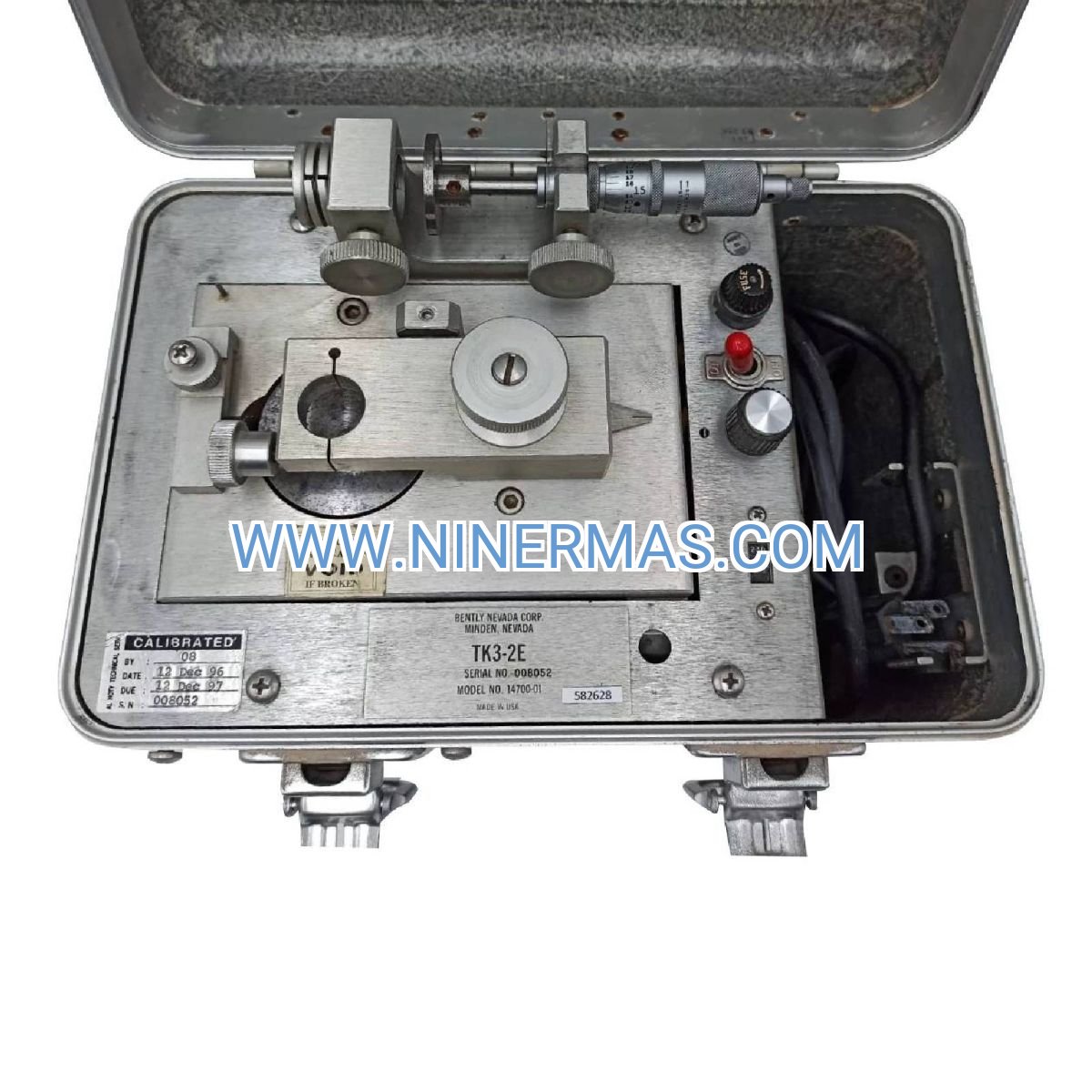

Contact Info
-
Address:22 / F, South Wo Hang building, 148 Wing Lok Street, Sheung Wan, Western District, Hong Kong
-
Phone:+8618750215667
-
Email: