


Description
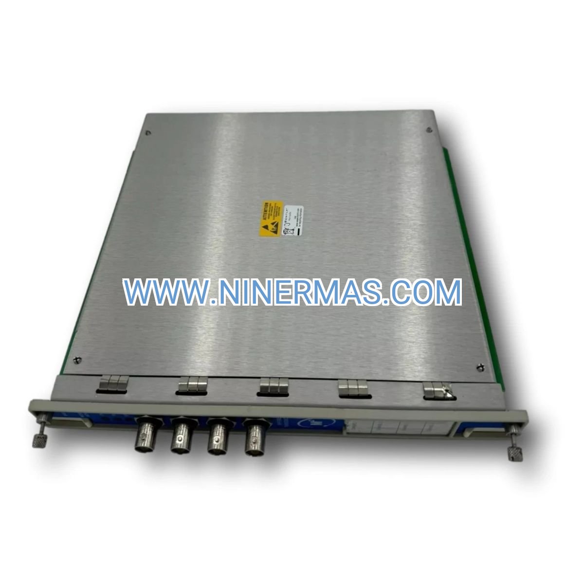
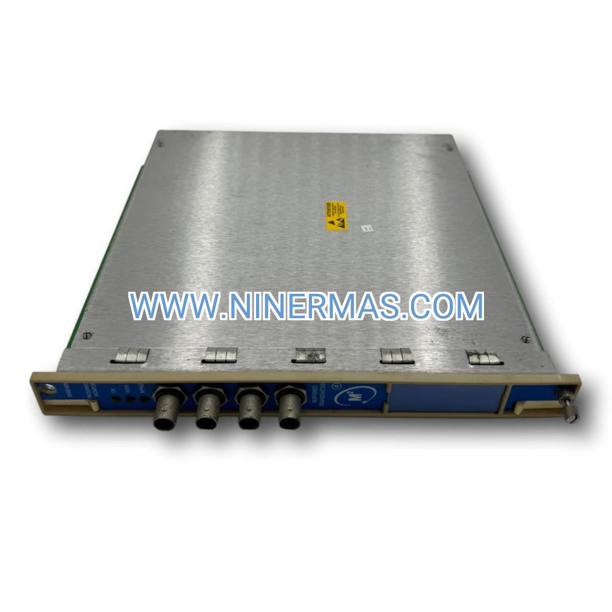
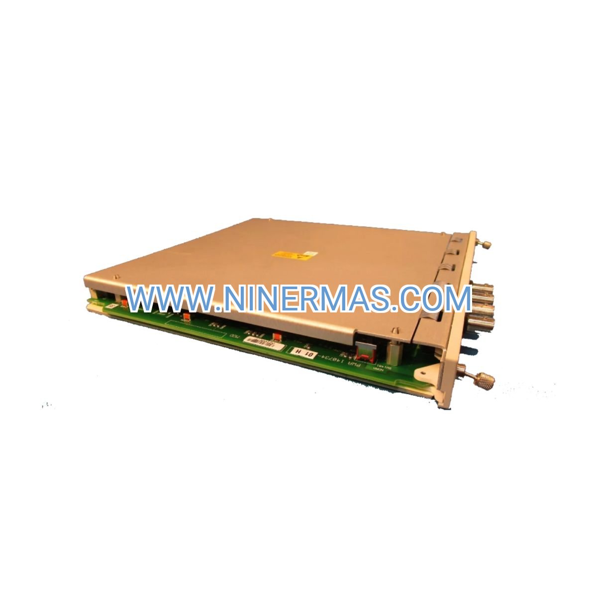
3500/33-03-00 Relay Output Module (Industrial-Grade 16-Channel Alarm Interface)
The 3500/33-03-00 delivers reliable alarm signal conversion for critical machinery protection applications. Engineered as part of the Bently Nevada 3500 monitoring platform, this 16-channel relay module transforms digital alarm data into hardwired contact closures, enabling seamless integration with emergency shutdown systems, distributed control networks, and plant-wide annunciation infrastructure.
Designed for power generation, oil & gas, and heavy industrial environments, the module supports complex voting logic, time-delay filtering, and multi-input Boolean operations—ensuring your protection strategy balances safety integrity with operational availability. Whether you're interfacing with legacy PLC systems or modern DCS architectures, the 3500/33 provides the flexibility and reliability demanded by SIL-rated safety functions.
With 16 independent SPDT relays rated for 5A switching capacity, programmable fail-safe modes, and hot-swap-ready terminal blocks, this module serves as the critical bridge between condition monitoring intelligence and automated protective action.
Core Features & Business Value
✓ 16 Independent SPDT Relay Channels
Each relay provides Form C contacts (NO, NC, Common) with 5A @ 30V DC / 250V AC rating, supporting diverse load types from low-voltage control circuits to annunciator panels. Eliminates the need for external relay amplifiers in most applications.
✓ Programmable Multi-Input Logic Engine
Configure each relay to respond to any combination of up to 128 alarm sources using AND, OR, NOT, and voting logic (2oo3, 2oo4). Reduces nuisance trips by 40-60% through intelligent alarm correlation while maintaining safety integrity per IEC 61508.
✓ Configurable Time Delays & Latching Modes
Pickup and dropout delays (0-60 seconds) filter transient alarms caused by process upsets or sensor noise. Optional latching behavior ensures operator acknowledgment before reset, meeting regulatory requirements for attended facilities.
✓ Fail-Safe Operation Architecture
Relays can be configured as normally energized (de-energize on alarm) for power-to-trip logic, ensuring safe shutdown during power loss or module failure. Critical for SIL 2/3 safety instrumented functions in turbomachinery protection.
✓ Universal DCS/PLC/ESD Integration
Dry contact outputs interface with any control system brand—Honeywell, Emerson, Siemens, ABB, Yokogawa—without protocol converters or gateways. Reduces integration costs by 30-50% compared to fieldbus-only solutions.
✓ Real-Time Diagnostic Visibility
16 individual status LEDs plus Module OK indicator provide instant visual confirmation of relay states. Software-based relay test function enables field wiring verification without triggering actual shutdowns.
Typical Application Scenarios
→ Steam Turbine Emergency Shutdown Systems
Implement 2oo3 voting logic on redundant vibration sensors to trip main stop valves when bearing vibration exceeds Danger setpoints. The module's 10 ms response time ensures protective action within turbine manufacturer specifications, preventing catastrophic blade rubs or bearing failures. Typical deployment: 2-4 relay modules per turbine train.
→ Compressor Anti-Surge Protection Interfaces
Provide hardwired trip signals to anti-surge valve controllers when discharge pressure, suction temperature, or vibration alarms activate. Programmable time delays (5-15 seconds) prevent valve cycling during normal load transients while ensuring rapid response to true surge conditions. Reduces compressor downtime by 25-35% versus single-point trip logic.
→ Refinery Pump Train Monitoring & Annunciation
Drive control room annunciator panels with staged alarm outputs: Relay 1 = Alert level (visual only), Relay 2 = Danger level (audible + visual), Relay 3 = Emergency shutdown (trip motor contactor). Operators gain 30-90 seconds of response time before automatic shutdown, reducing production losses from false trips.
→ Offshore Platform Unmanned Operation
Activate radio telemetry units or cellular modems when critical alarms occur at remote wellhead compressors or gas lift systems. Latching relay mode ensures alarm state is maintained until maintenance personnel arrive and manually reset, meeting offshore safety case requirements.
→ Power Plant Auxiliary Systems Interlocking
Implement complex interlock sequences using Boolean logic: prevent boiler feed pump startup if lube oil pressure < 15 psig AND bearing temperature > 180°F. Single relay module replaces 8-12 discrete relay panels, reducing panel space by 60% and wiring labor by 40%.
Technical Parameters & Selection Guide
| Parameter | Specification | Selection Notes |
|---|---|---|
| Relay Channels | 16 independent SPDT (Form C) | Use 3500/32 (4-channel) for smaller racks |
| Contact Rating | 5A @ 30V DC / 250V AC resistive | Derate to 3A for inductive loads; use external contactors for >5A |
| Switching Capacity | 150W DC, 1250 VA AC max | Install RC snubbers (0.1µF + 100Ω) for solenoid/contactor loads |
| Operating Time | 10 ms energize, 5 ms de-energize | Meets API 670 response time requirements for machinery protection |
| Mechanical Life | 10 million operations minimum | Electrical life: 100,000 ops @ rated load; replace after 10 years or 100k cycles |
| Alarm Inputs | Up to 128 sources per relay | Any monitor module in 3500 rack; supports cross-rack alarm mapping |
| Logic Functions | AND, OR, NOT, 2oo3, 2oo4 voting | Configure via 3500 Rack Configuration Software; offline simulation available |
| Time Delays | 0-60 seconds pickup/dropout | Typical settings: 2-5 sec for vibration, 10-30 sec for temperature alarms |
| Operating Temp | -30°C to +65°C (-22°F to +149°F) | Install in climate-controlled enclosure for extreme environments |
| Power Consumption | 12W max (all relays energized) | Supplied from 3500 rack backplane; no external power required |
| Slot Position | Any slot in 3500 rack | Typically install in rightmost slots for easier field wiring access |
| Modules per Rack | Up to 4 relay modules (64 relays) | Limited by rack slot count and power budget |
Selection Criteria: Choose the 3500/33 (16-channel) for applications requiring >8 alarm outputs or complex multi-input logic. For simple alarm forwarding with ≤4 outputs, the 3500/32 (4-channel) offers lower cost. For SIL 2/3 applications, deploy redundant relay modules with diverse logic to achieve required safety integrity levels.
Extended Functions & IoT Integration
Remote Monitoring Connectivity: Relay outputs can drive industrial IoT gateways (Modbus RTU, HART, OPC UA) to transmit alarm states to cloud-based condition monitoring platforms. Typical integration: relay contacts trigger digital inputs on edge devices, which publish MQTT messages to AWS IoT Core or Azure IoT Hub for predictive maintenance analytics.
Cybersecurity Considerations: As a hardwired relay module, the 3500/33 provides inherent cyber-physical isolation—alarm signals cannot be compromised via network attacks. Recommended for critical safety functions in IEC 62443-compliant architectures where air-gapped protection layers are mandated.
Customization Options: Factory configuration services available for pre-programmed relay logic, custom terminal labeling, and extended temperature range (-40°C to +70°C) for Arctic or desert installations. Contact technical sales for MOQ and lead times.
Delivery Timeline & Service Guarantee
Standard Lead Time: 3-5 business days for in-stock units (North America, Europe, Asia-Pacific warehouses). Expedited 24-48 hour shipping available for emergency shutdowns or unplanned outages—contact sales for rush order processing.
Custom Configuration: 10-15 business days for factory-programmed modules with customer-specific relay logic and terminal labeling. Includes offline simulation testing and configuration file documentation.
Warranty Coverage: 24-month manufacturer warranty covering defects in materials and workmanship. Extended 60-month warranty available for applications with <10,000 annual relay operations. Warranty includes advance replacement for critical spares programs.
Technical Support: Lifetime application engineering support via phone, email, and remote desktop. Typical response time: <4 hours for critical alarms, <24 hours for configuration assistance. On-site commissioning and troubleshooting services available in major industrial regions.
Documentation Package: Includes product datasheet, wiring diagrams, relay logic configuration examples, IEC 61508 functional safety manual, and 3500 Rack Configuration Software installer. All documents provided in PDF format with purchase.
Frequently Asked Questions
Q: How do I connect the 3500/33 relay module to my existing DCS system?
A: The module uses removable screw-terminal blocks accepting 12-22 AWG wire. Connect relay Common and NO (or NC) terminals to your DCS digital input card. Typical wiring: relay Common to DCS common, relay NO to DCS input (+). Ensure DCS input voltage rating matches relay contact rating (typically 24V DC). Refer to Section 4.2 of the installation manual for detailed wiring diagrams.
Q: What relay contact capacity do I need for driving a 120V AC solenoid valve?
A: The 3500/33 relays are rated 5A @ 250V AC resistive. For inductive loads like solenoid valves, derate to 60% (3A) and install an RC snubber (0.1 µF capacitor + 100Ω resistor in series) across the relay contacts to suppress inrush current and extend contact life. For loads >3A, use the relay to switch an external contactor rated for the solenoid's full inrush current.
Q: Can the relay module help reduce false trips in our compressor protection system?
A: Yes—configure 2-out-of-3 (2oo3) voting logic on redundant vibration sensors. The relay only energizes when two of three sensors exceed the Danger setpoint, filtering single-sensor failures or transient spikes. Additionally, set pickup delays (5-10 seconds) to ignore momentary vibration during load changes. Customers report 40-60% reduction in nuisance trips using these techniques.
Q: What are the installation requirements for hazardous area applications?
A: The 3500/33 is suitable for Class I Division 2 Groups A, B, C, D locations when installed per NEC Article 501. Mount the 3500 rack in a NEMA 4X or IP66 enclosure with purge/pressurization if required. Ensure all relay wiring uses intrinsically safe barriers or galvanic isolators when connecting to Zone 0/1 field devices. Consult your site's electrical classification drawings and AHJ for specific requirements.
Q: How often should I perform relay contact maintenance and testing?
A: Annual inspection recommended: measure contact resistance using a milliohm meter (replace module if >50 mΩ), verify LED operation, check terminal torque (0.5-0.6 N⋅m). For SIL-rated safety functions, perform quarterly proof testing per IEC 61508—manually trip each relay via software and verify field device response. Replace module after 100,000 operations at rated load or 10 years, whichever comes first.
Q: Can I monitor relay operation counts for predictive maintenance?
A: Yes—the 3500 Rack Configuration Software logs relay activation timestamps, durations, and cumulative operation counts. Export this data to CSV for trending in your CMMS or predictive maintenance platform. Set up automatic alerts when relays approach 80,000 operations (80% of rated electrical life) to schedule proactive replacement during planned outages.
Take the Next Step
Ready to enhance your machinery protection system with proven relay interface technology? Our application engineers are standing by to help you configure the optimal alarm logic for your specific process conditions.
Request a Technical Consultation: Share your P&ID, alarm philosophy document, and DCS I/O list—we'll provide a detailed relay mapping proposal within 48 hours, including logic diagrams, wiring schedules, and bill of materials.
Order Now: In-stock units ship within 24 hours. Need help with part number selection or quantity discounts for multi-unit projects? Contact our sales team at sale@ninermas.com or call +0086 187 5021 5667 (English/Mandarin support available 24/7).
Download Resources: Access installation manuals, configuration software, and relay logic examples at our technical library: https://ninermas.com
© 2026 NINERMAS COMPANY LIMITED. All rights reserved.
Original Source: https://ninermas.com
Contact: sale@ninermas.com | +0086 187 5021 5667
PDF Specification
Download PDF file here:
Click to Download PDF


Contact Info
-
Address:22 / F, South Wo Hang building, 148 Wing Lok Street, Sheung Wan, Western District, Hong Kong
-
Phone:+8618750215667
-
Email: