Description
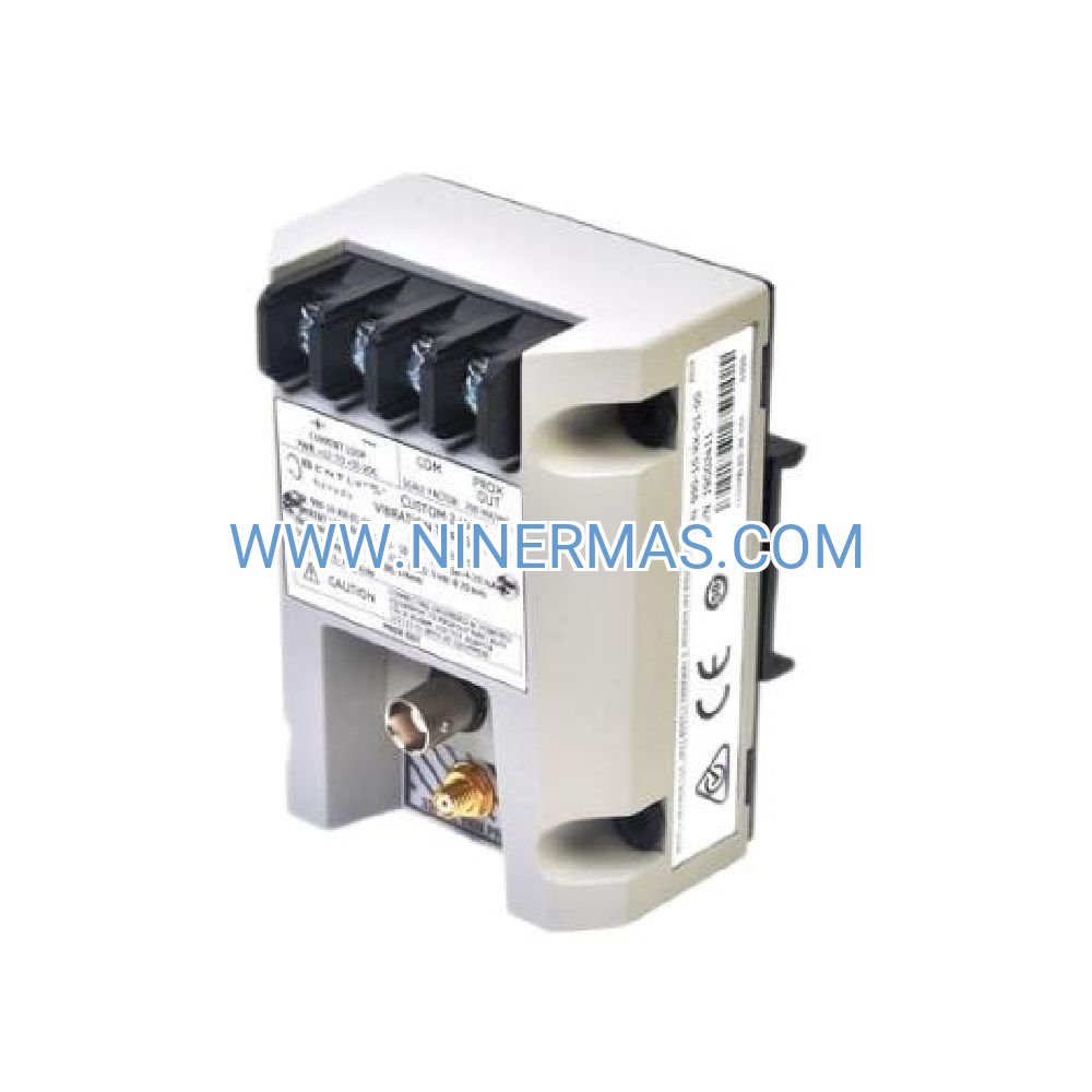
3500/25-02-01-00 Keyphasor I/O Module (Industrial-Grade Timing Reference System)
The Bently Nevada 3500/25-02-01-00 represents a critical timing reference component within the 3500 Series machinery protection platform. Engineered with dual independent channels, this keyphasor I/O module transforms proximity probe signals into precision digital timing markers, delivering the foundational data required for rotor speed tracking, phase angle diagnostics, and vibration vector analysis across turbomachinery installations.
Designed for power generation facilities, petrochemical plants, and heavy industrial operations, the 3500/25 module addresses the fundamental challenge of correlating vibration events with shaft rotational position. By providing microsecond-accurate timing references distributed across the entire monitoring rack, this module enables predictive maintenance teams to distinguish between mechanical faults—such as unbalance, misalignment, and shaft cracks—that would otherwise appear identical in frequency-domain analysis alone.
With field-proven reliability exceeding 200,000-hour MTBF and compatibility across all 3500 rack configurations, the 3500/25-02-01-00 serves as the synchronization backbone for comprehensive condition monitoring programs protecting assets valued in the tens of millions of dollars.
Core Capabilities & Technical Advantages
✓ Dual Independent Input Channels – Monitor two separate shafts simultaneously or implement primary/backup redundancy for mission-critical applications; each channel processes 0.1 Hz to 10 kHz (6-600,000 RPM) with ±0.01% speed accuracy and ±1° phase resolution above 600 RPM
✓ Adaptive Signal Conditioning – Proprietary Schmitt trigger architecture with auto-adjusting threshold maintains 50% amplitude triggering across varying probe gaps, rejecting transient noise spikes below 50 μs while delivering <10 ns edge transition times for precision phase measurement
✓ Universal Rack Integration – Installs in any slot position within 3500/05 system racks (2-slot through 17-slot configurations); distributes keyphasor timing to all monitor modules via proprietary backplane with <1 μs propagation delay and 1500V DC channel-to-backplane isolation
✓ Multi-Notch Processing – Supports single or multiple events per revolution for high-resolution angular position tracking in slow-speed machinery and reciprocating equipment; missing pulse detection identifies damaged notches or probe misalignment before data integrity is compromised
✓ Diagnostic Transparency – Dual-channel status LEDs provide real-time visual confirmation of pulse activity; configuration software displays live speed, pulse width, signal amplitude, and trigger threshold for each input with fault event logging and timestamping
✓ Harsh Environment Resilience – Operates reliably across -30°C to +65°C ambient temperatures and 5-95% non-condensing humidity; UL 508 Listed, CE marked, and DNV GL Type Approved for marine installations with Class I Division 2 hazardous location suitability
Industrial Application Scenarios
→ Steam Turbine-Generator Sets
In 3600 RPM turbine-generator trains, the 3500/25 module provides the phase reference essential for detecting thermal bows during startup, identifying rub events through sudden phase angle shifts, and validating coupling alignment by comparing vibration phase relationships between bearing positions. Maintenance teams use keyphasor-synchronized orbit analysis to distinguish between steam-induced excitation and mechanical looseness.
→ Gas Turbine Compressor Trains
For aero-derivative and industrial gas turbines driving centrifugal compressors, dual-channel keyphasor monitoring enables simultaneous tracking of turbine and compressor shaft speeds. This configuration supports differential speed measurement for fluid coupling slip calculation, critical speed mapping during startup transients, and surge detection through phase-resolved vibration analysis of multi-stage compression events.
→ Large Induction Motor Diagnostics
Electrical fault diagnosis in motors rated above 1000 HP requires phase-angle discrimination between 2× line frequency electrical issues and mechanical problems. The 3500/25 module's precision timing reference allows vibration analysts to separate rotor bar defects (producing slip-frequency sidebands) from bearing wear (generating non-synchronous components) through phase-locked spectral analysis.
→ Reciprocating Compressor Monitoring
Reciprocating machinery presents unique diagnostic challenges requiring correlation of vibration events with specific crank angles. By processing multi-notch keyphasor signals (typically 4-8 events per revolution), the 3500/25 enables identification of valve impact timing, crosshead wear patterns, and rod drop conditions through angle-domain averaging and order tracking techniques.
→ Gearbox Health Assessment
Dual-channel architecture proves invaluable in gearbox monitoring applications where input and output shaft speeds must be tracked simultaneously. Maintenance teams calculate real-time gear ratios to detect tooth wear progression, identify bearing degradation through modulation analysis, and validate lubrication system effectiveness by monitoring speed-dependent vibration trends.
Technical Specifications & Selection Criteria
| Model Designation | 3500/25-02-01-00 |
| Input Configuration | 2 independent keyphasor channels |
| Sensor Compatibility | Proximity probe (eddy current transducer), -24V DC nominal |
| Trigger Threshold | -7V DC typical (field-adjustable -5V to -9V) |
| Speed Range | 0.1 Hz to 10 kHz (6 RPM to 600,000 RPM) |
| Speed Accuracy | ±0.01% of reading |
| Phase Resolution | ±1° electrical at speeds >600 RPM |
| Minimum Pulse Width | 100 μs for reliable triggering |
| Channel Isolation | 1500V DC channel-to-backplane |
| Power Consumption | 3.5W from 3500 rack supply |
| Operating Temperature | -30°C to +65°C (-22°F to +149°F) |
| Dimensions (W×H×D) | 24.4 × 241.8 × 241.3 mm (0.96" × 9.52" × 9.50") |
| Weight | 0.46 kg (1.01 lbs) |
Selection Guidance: Choose the 3500/25-02-01-00 when your application requires dual-channel keyphasor capability for multi-shaft monitoring, redundant signal acquisition, or differential speed measurement. For single-shaft applications with basic speed monitoring needs, consider the single-channel 3500/25-01 variant. Ensure your proximity probe system delivers -24V DC nominal output voltage and that shaft notch geometry meets minimum 0.125" depth × 0.25" width specifications for reliable signal generation.
Advanced Diagnostic Techniques Enabled
The keyphasor timing reference unlocks sophisticated analysis methodologies that transform raw vibration data into actionable maintenance intelligence:
Orbit Analysis – Combining X-Y proximity probe measurements with keyphasor timing generates real-time shaft orbit displays revealing rotor centerline motion, precession direction, and dynamic load distribution. Maintenance teams identify rub severity, quantify bearing clearance changes, and validate alignment corrections through orbit shape analysis.
Bode Plot Generation – Plotting vibration amplitude and phase angle versus rotational speed during startup/shutdown transients maps critical speeds, quantifies damping ratios, and validates rotor dynamic models. Phase angle transitions of 180° confirm resonance passage, while amplitude peaks identify speeds requiring operational restrictions.
Polar Vector Displays – Representing vibration as magnitude and phase angle in polar coordinates visualizes unbalance distribution across multiple speeds. Balancing technicians optimize correction plane selection and minimize residual vibration by analyzing vector changes before and after trial weight additions.
Full Spectrum Analysis – Separating forward and backward shaft precession components using keyphasor phase reference enables early detection of fluid-induced instabilities such as oil whirl and oil whip in journal bearings. This technique distinguishes between destabilizing forces and mechanical excitation that conventional FFT analysis cannot resolve.
Order Tracking – Synchronizing vibration analysis to shaft rotation rather than time domain isolates gear mesh frequencies, blade pass frequencies, and other speed-dependent phenomena from non-synchronous components. This approach proves essential for diagnosing faults in variable-speed machinery where traditional frequency analysis fails.
Installation & Commissioning Protocol
Proximity Probe Mounting: Position probe to view once-per-revolution notch, keyway, or pin on shaft surface; maintain 40-80 mil (1.0-2.0 mm) gap for optimal signal amplitude. Notch must provide minimum 0.125" (3.2 mm) depth and 0.25" (6.4 mm) width with sharp edges for clean signal transitions.
Cable Infrastructure: Use shielded extension cable (Belden 9534 or equivalent) with maximum total length of 300 feet (91 meters) including probe cable. Connect shield to ground at proximitor sensor end only to prevent ground loops; verify cable capacitance remains within proximitor specifications.
Module Configuration: Install 3500/25 module in any available rack slot (typically Slot 2 or 3 for convenient access). Power down rack before insertion; module is not hot-swappable. Use 3500 Rack Configuration Software to adjust trigger threshold to 50% of peak-to-peak signal amplitude for optimal noise immunity.
Signal Verification: Rotate shaft and confirm clean square-wave output with pulse width representing 10-30% of revolution period. Dual-channel status LEDs should flash at keyphasor pulse rate. Compare keyphasor-derived speed with independent tachometer reading to verify accuracy within ±0.01%.
Monitor Module Assignment: Configure each vibration monitor module (3500/40M, 3500/42M, 3500/46M, etc.) to select appropriate keyphasor input (Channel 1 or 2) for phase reference. Verify keyphasor timing distribution across all monitors through configuration software diagnostics.
Extended Functionality & System Integration
Redundant Signal Architecture: Dual-channel design supports primary/backup probe configurations where two keyphasor probes view the same shaft. If the primary probe fails due to cable damage or sensor degradation, monitor modules automatically switch to the backup channel, maintaining continuous phase reference without manual intervention.
Multi-Shaft Coordination: In train configurations with multiple rotating elements (e.g., motor-gearbox-compressor), the 3500/25 module monitors two shafts from a single slot, reducing rack space requirements and system cost while enabling differential speed calculations for slip measurement and gear ratio verification.
Configuration Software Integration: The 3500 Rack Configuration Software provides comprehensive setup and diagnostic capabilities including real-time speed display, pulse width measurement, signal amplitude monitoring, threshold adjustment, and fault event logging with timestamp correlation to process events.
Data Management System Connectivity: Keyphasor timing and speed data integrate with System 1 condition monitoring software, enabling long-term trend analysis, automated alarm generation, and correlation with process parameters such as load, temperature, and pressure for root cause analysis.
Delivery Timeline & Service Commitment
Standard Lead Time: 3-5 business days for in-stock units; expedited same-day shipping available for critical outage support
Warranty Coverage: 12-month manufacturer warranty covering defects in materials and workmanship; extended warranty options available for long-term service agreements
Technical Support: Pre-sales application engineering assistance for system design; post-sales commissioning support via phone, email, and remote desktop; on-site startup services available upon request
Documentation Package: Complete product manual, installation guide, configuration software, and application notes for vibration analysis techniques; CAD drawings and 3D models available for system integration planning
Frequently Asked Questions
Q: Can the 3500/25 module process keyphasor signals from magnetic pickup sensors or optical encoders?
A: No, the 3500/25-02-01-00 is designed exclusively for proximity probe (eddy current transducer) inputs providing -24V DC nominal output. Magnetic pickups and optical encoders require different signal conditioning and should use the 3500/50 tachometer module instead.
Q: What is the maximum cable length between the proximity probe and the 3500/25 module?
A: Total cable length including probe cable and extension cable should not exceed 300 feet (91 meters). Longer cable runs increase capacitance, which can degrade signal quality and reduce the effective frequency response of the proximity probe system.
Q: How does the dual-channel configuration improve system reliability compared to single-channel modules?
A: Dual-channel architecture enables primary/backup redundancy where two probes monitor the same shaft. If the primary probe fails, monitor modules automatically reference the backup channel, maintaining continuous phase measurement without system downtime or manual reconfiguration.
Q: Can I use the 3500/25 module to monitor machinery operating below 60 RPM?
A: Yes, the module's frequency response extends down to 0.1 Hz (6 RPM). However, at very low speeds, ensure your proximity probe system can maintain adequate signal amplitude and that the keyphasor notch geometry provides sufficient depth for reliable triggering at extended probe gaps.
Q: What diagnostic information indicates that my keyphasor signal quality is degrading?
A: Warning signs include intermittent LED activity, erratic speed readings, increasing pulse width variation, and declining signal amplitude shown in configuration software. These symptoms typically indicate probe gap changes, notch wear, cable degradation, or electrical noise interference requiring investigation.
Q: Is the 3500/25 module compatible with legacy 3300 Series monitoring systems?
A: No, the 3500/25 module is designed exclusively for 3500 Series racks and is not backward-compatible with 3300 Series systems. The backplane architecture, power requirements, and communication protocols differ between these platforms.
Request Technical Consultation
Our application engineering team provides complimentary pre-sales support to ensure optimal product selection for your machinery protection requirements. Contact us with your shaft speed range, number of monitoring points, environmental conditions, and hazardous area classification for personalized recommendations and system architecture guidance.
© 2026 NINERMAS COMPANY LIMITED. All rights reserved.
Original Source: https://ninermas.com
Contact: sale@ninermas.com | +0086 187 5021 5667
PDF Specification
Download PDF file here:
Click to Download PDF

Contact Info
-
Address:22 / F, South Wo Hang building, 148 Wing Lok Street, Sheung Wan, Western District, Hong Kong
-
Phone:+8618750215667
-
Email: