Description
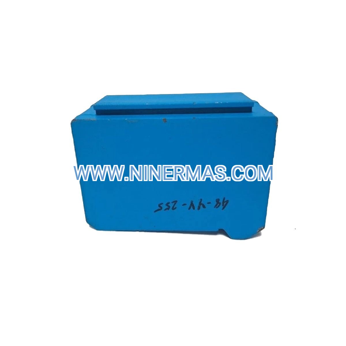
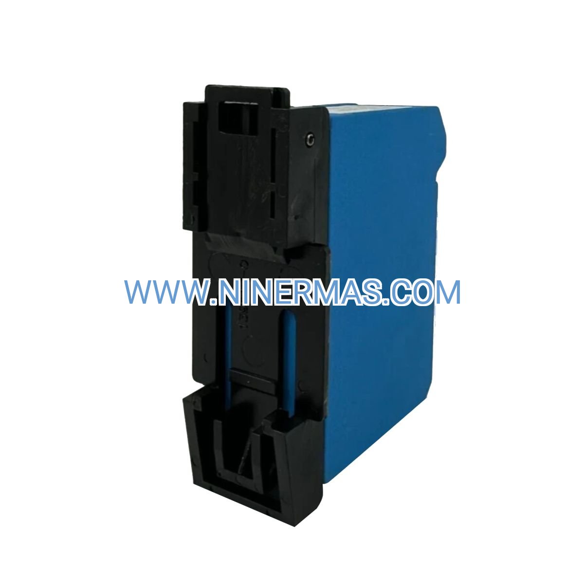
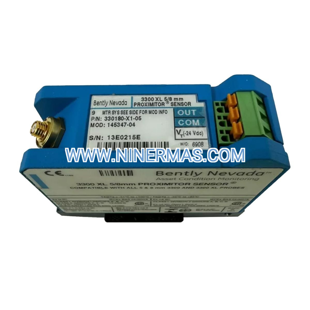
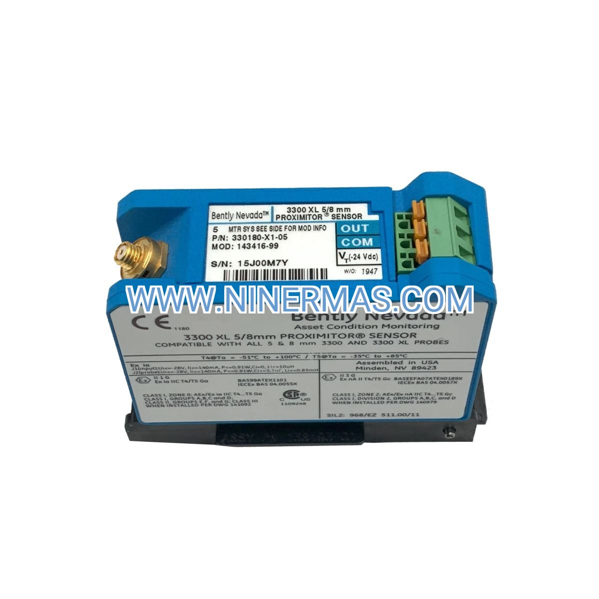
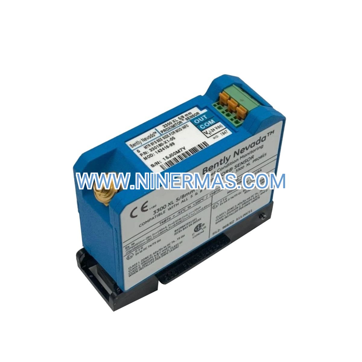
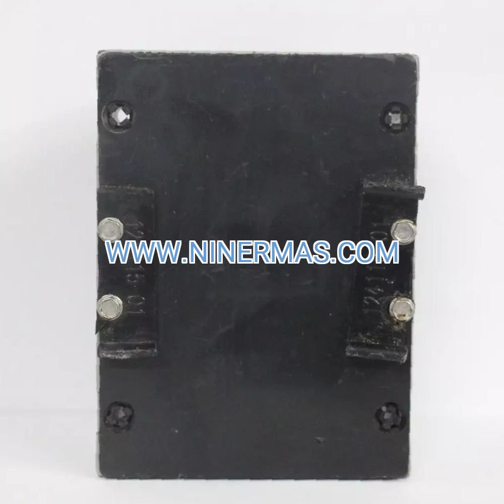
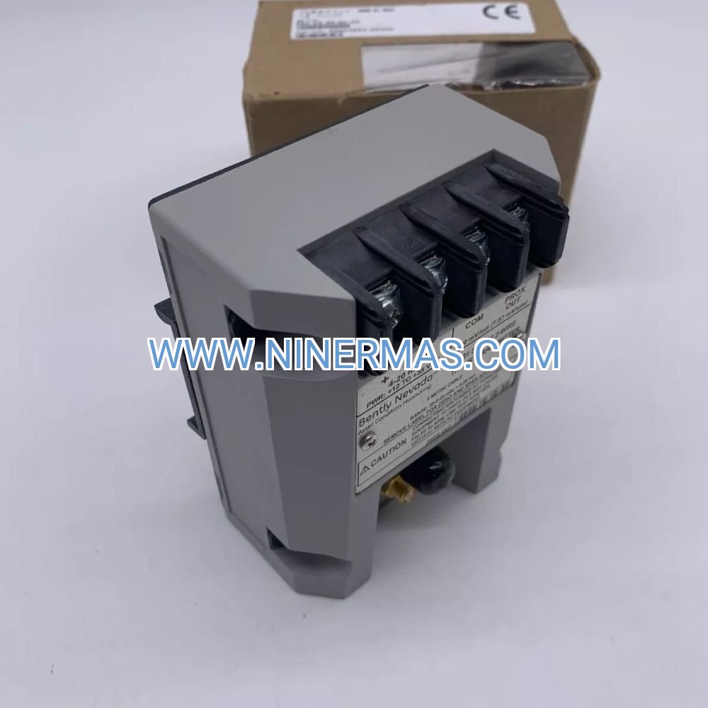
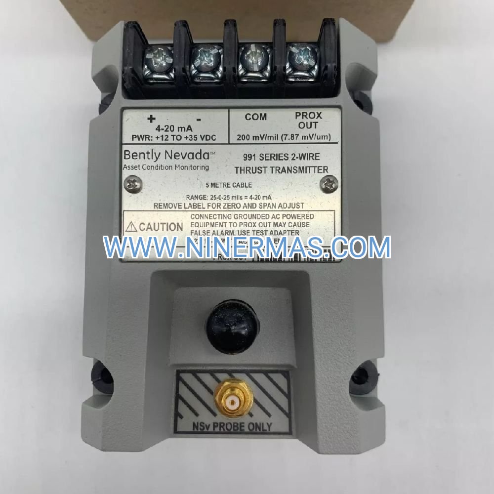
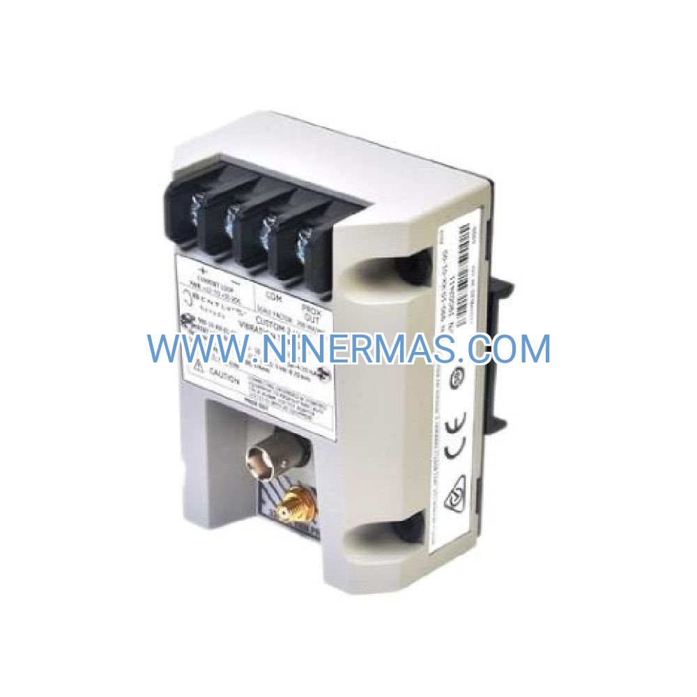
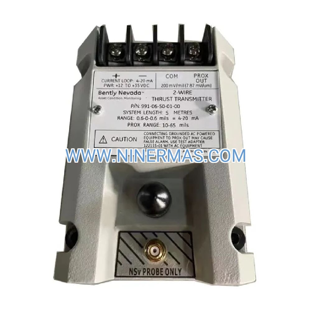
Bently Nevada 330180-X1-05 MOD 145193-01 Proximity Transducer System (Industrial-Grade Vibration Monitoring Solution)
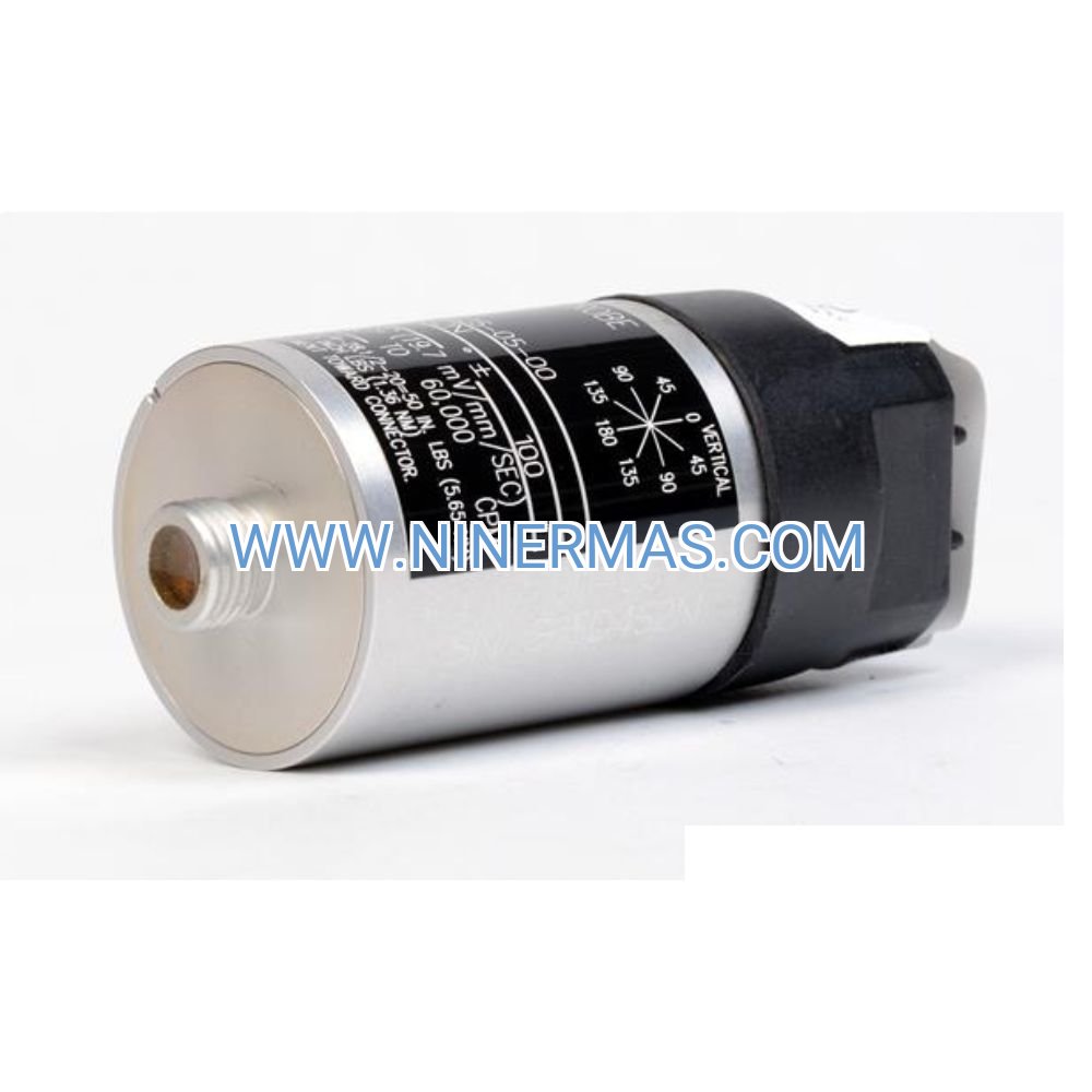
The Bently Nevada 330180-X1-05 MOD 145193-01 is an industrial-grade proximity transducer system engineered for continuous vibration and displacement monitoring in critical rotating machinery. Through integrated 8mm probe technology and factory-calibrated proximitor conditioning, this system delivers real-time shaft position data with ±2% linearity across the full measurement range, enabling predictive maintenance strategies and preventing catastrophic equipment failures.
Designed for high-reliability applications in power generation, oil & gas processing, and heavy industrial environments, the 330180-X1-05 addresses common challenges including bearing wear detection, shaft eccentricity measurement, thrust position monitoring, and differential expansion tracking. Suitable for design engineers, maintenance teams, system integrators, and plant operators managing steam turbines, centrifugal compressors, large electric motors, and critical pump assemblies.
Built on proven 3300 XL platform architecture with API 670 compliance and ISO 20816 alignment, this transducer system offers seamless integration with existing monitoring infrastructure, extended temperature range (-40°C to +85°C), and comprehensive protection features. Contact our application engineers for customized configuration recommendations, installation support, and technical specifications tailored to your machinery protection requirements.
Core Features & Technical Advantages
- High-Precision Measurement Capability
Factory-calibrated 8mm proximity probe delivers ±2% linearity over 0.5-2.5mm range with -2 to -18 Vdc output signal proportional to target gap, ensuring accurate shaft displacement data for condition-based maintenance decisions. - Wide Frequency Response for Dynamic Monitoring
DC to 10 kHz bandwidth (-3dB point) captures both slow-roll baseline measurements and high-frequency vibration events, providing complete machinery health visibility from startup through full-speed operation. - Extreme Environment Durability
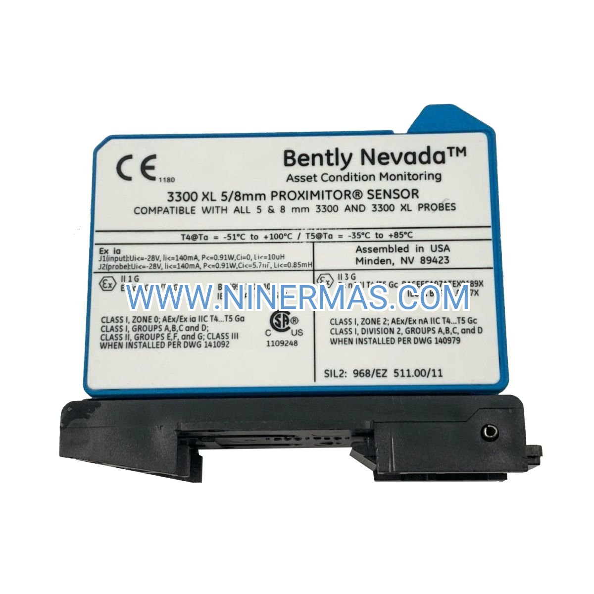
Operates reliably across -40°C to +85°C temperature range with hermetically sealed probe construction and industrial-grade proximitor electronics, minimizing false alarms and maintenance interventions in harsh process environments. - API 670 Compliance & Standards Alignment
Meets petroleum and natural gas industry machinery protection system requirements (API 670 4th Edition), ensuring compatibility with safety instrumented systems and regulatory compliance for critical equipment installations. - Plug-and-Play System Integration
Pre-matched probe and proximitor configuration eliminates field calibration requirements, reducing commissioning time by up to 60% compared to component-based systems while maintaining measurement accuracy and traceability. - Comprehensive Diagnostic Capabilities
Built-in OK/Alert status indication, cable fault detection, and target material verification features enable rapid troubleshooting and reduce mean time to repair (MTTR) during maintenance activities.
Typical Application Scenarios
This proximity transducer system is engineered for machinery protection applications requiring continuous non-contact displacement measurement, particularly in:
- Steam & Gas Turbine Monitoring
Tracks radial shaft vibration, thrust bearing position, and differential expansion in power generation turbines, preventing blade rubs and bearing failures through early fault detection in 50-500 MW class machines. - Centrifugal Compressor Protection
Monitors shaft displacement and axial position in multi-stage compressors serving petrochemical, LNG, and air separation plants, safeguarding against surge conditions and mechanical seal damage in API 617 equipment. - Critical Pump Vibration Analysis
Provides real-time eccentricity and radial position data for boiler feed pumps, pipeline transfer pumps, and refinery process pumps, enabling condition-based maintenance and reducing unplanned downtime costs. - Large Motor & Generator Sets
Measures rotor position and bearing clearance in synchronous motors, induction motors above 500 HP, and hydroelectric generators, supporting alignment verification and long-term bearing wear trending. - Gearbox & Coupling Monitoring
Detects shaft misalignment, gear mesh issues, and coupling wear in industrial gearboxes and flexible coupling assemblies, preventing secondary damage to connected equipment through early intervention.
Technical Parameters & Selection Guide
To facilitate engineering design and system specification, we provide standardized technical parameters for the 330180-X1-05 MOD 145193-01 configuration. Custom probe lengths, cable extensions, and mounting hardware are available for project-specific requirements.
| Parameter | Specification |
|---|---|
| Probe Diameter | 8mm (0.315 inch) standard industrial |
| Measurement Range | 0.5 to 2.5mm (20 to 100 mils) calibrated span |
| Frequency Response | DC to 10 kHz (-3dB), 0 to 25 kHz (-10dB) |
| Output Signal | -2 to -18 Vdc (proportional to gap) |
| Linearity Error | ±2% of full scale over calibrated range |
| Operating Temperature | -40°C to +85°C (-40°F to +185°F) |
| Power Supply (Proximitor) | -24 Vdc ±10% (typical 3300 XL configuration) |
| Target Material | Ferromagnetic (4140 steel equivalent or better) |
| Compliance Standards | API 670 4th Edition, ISO 20816 aligned |
| Environmental Rating | IP65 probe housing (when properly installed) |
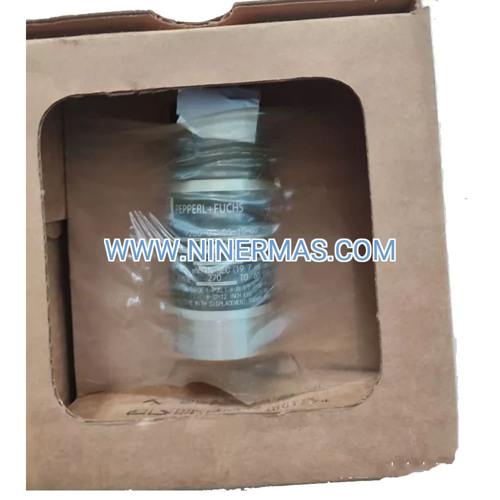
| System Configuration | Integrated probe + proximitor (MOD 145193-01) |
Selection Considerations: When specifying this transducer system, engineers should evaluate target shaft material composition, available mounting space and thread compatibility, required cable run length to monitoring rack, ambient temperature extremes, and integration requirements with DCS/PLC systems. For applications requiring extended probe lengths beyond standard configurations, custom cable assemblies with impedance-matched extension cables are recommended. Our application engineering team can assist with probe mounting design, gap voltage calculations, and system commissioning procedures—please provide machinery type, shaft diameter, operating speed range, and monitoring objectives for tailored recommendations.
Advanced Integration & Connectivity Options
The 330180-X1-05 MOD 145193-01 integrates seamlessly with comprehensive machinery monitoring architectures:
- Multi-Channel Monitoring Racks: Compatible with 3300 XL rack-mount systems supporting 4-16 channel configurations for complete machine train monitoring
- Digital Communication Interfaces: Outputs interface with 4-20mA converters, Modbus RTU gateways, and OPC-UA servers for SCADA/DCS integration
- Redundant Measurement Configurations: Supports dual-probe XY vibration monitoring and triple-modular redundant (TMR) safety systems per IEC 61508
- Data Acquisition Compatibility: Direct connection to high-speed DAQ systems (National Instruments, Brüel & Kjær, Crystal Instruments) for FFT analysis and order tracking
- Wireless Monitoring Adaptation: Proximitor output compatible with wireless vibration transmitters for remote or hazardous area installations
Delivery, Service & Quality Assurance
Lead Time & Availability: Standard 330180-X1-05 MOD 145193-01 configurations typically ship within 3-5 business days from stock. Custom probe lengths or special cable configurations require 10-15 business days for factory assembly and calibration verification.
Warranty Coverage: All transducer systems include a comprehensive 18-month warranty from shipment date, covering manufacturing defects, calibration drift beyond published specifications, and component failures under normal operating conditions. Extended warranty programs available for critical equipment applications.
Technical Support Services: Complimentary installation guidance via phone/email during commissioning phase. On-site startup assistance and training available (subject to location and scope). Remote diagnostic support for troubleshooting signal anomalies or system integration challenges.
Documentation Package: Each system ships with factory calibration certificate (traceable to NIST standards), dimensional installation drawings, electrical connection diagrams, proximitor wiring schematics, gap voltage reference tables, and quick-start commissioning checklist. Complete technical manuals available in PDF format upon request.
Quality Certifications: Manufactured under ISO 9001:2015 quality management system with 100% functional testing, temperature cycle screening, and multi-point calibration verification prior to shipment. Certificate of Conformance (C of C) and Material Test Reports (MTR) available for critical applications.
Frequently Asked Questions (FAQ)
Q: How does the 330180-X1-05 proximity transducer integrate with existing 3300 XL monitoring systems?
A: The system uses standard 3300 XL electrical interfaces and mounting configurations, allowing direct replacement of legacy sensors or expansion of existing monitoring channels. The proximitor output (-2 to -18 Vdc) connects to monitor input modules, recorders, or protection relay systems using standard coaxial cabling. Verify power supply compatibility (-24 Vdc typical) and confirm mounting thread specifications (typically 3/8-24 UNF or M10x1) before installation.
Q: What is the maximum number of transducers that can be monitored on a single rotating machine?
A: Typical turbomachinery installations use 2-4 proximity probes per bearing (XY radial pairs), plus 1-2 axial position sensors and optional keyphasor reference probes. A complete steam turbine train might employ 12-20 proximity channels across multiple bearings and coupling sections. System architecture depends on machinery criticality, API 670 requirements, and specific monitoring objectives—consult with vibration specialists for optimal sensor placement strategies.
Q: Can this proximity transducer system achieve energy savings or efficiency improvements?
A: While the transducer itself does not directly reduce energy consumption, the continuous monitoring capability enables condition-based maintenance strategies that prevent efficiency-degrading faults. Early detection of bearing wear, misalignment, or rotor rubs maintains optimal machinery efficiency and avoids the 5-15% performance degradation typical of undetected mechanical issues. Predictive maintenance programs using proximity data can reduce unplanned downtime by 30-50% and extend equipment service life by 20-40%.
Q: What are the installation environment requirements and protection class specifications?
A: The 8mm proximity probe is designed for direct mounting in machinery bearing housings or pedestal assemblies, with IP65 environmental protection when properly installed with thread sealant and cable glands. The proximitor signal conditioner typically mounts in climate-controlled instrument rooms or NEMA 4X enclosures. Avoid direct exposure to corrosive chemicals, continuous water immersion, or temperatures exceeding +85°C. For hazardous area installations (Class I Div 2, ATEX Zone 2), consult factory for intrinsically safe barrier requirements and certifications.
Q: Does the system support remote monitoring, data logging, and wireless connectivity?
A: The proximitor analog output (-2 to -18 Vdc) can interface with various remote monitoring solutions including 4-20mA transmitters with HART protocol, wireless vibration gateways (WirelessHART, ISA100), and cloud-connected IIoT platforms. For comprehensive data logging, the output connects to DCS historian systems, standalone data recorders, or edge computing devices running vibration analysis software. Modbus RTU/TCP and OPC-UA gateways enable integration with plant-wide asset management systems and predictive analytics platforms.
Q: What calibration and maintenance procedures are required over the system's operational life?
A: The factory calibration remains stable for 3-5 years under normal operating conditions, with annual verification recommended for critical safety applications. Maintenance consists primarily of periodic cable inspection, connector cleaning, and gap voltage verification using a digital multimeter. No field recalibration is typically required unless physical damage occurs or the probe/proximitor is separated. Replacement proximitors must be matched to the original probe serial number to maintain calibration accuracy—contact technical support for recalibration services or matched component replacement procedures.
Request Custom Configuration & Technical Support
To receive detailed application engineering support, customized system specifications, or project quotations, please provide the following information to our technical team:
- Machinery type and model (turbine, compressor, pump, motor, etc.)
- Shaft diameter and material composition at measurement location
- Operating speed range (RPM) and maximum vibration amplitude expectations
- Number of measurement points and monitoring objectives (radial, axial, differential expansion)
- Mounting constraints (thread size, probe length, cable run distance)
- Environmental conditions (temperature range, hazardous area classification)
- Integration requirements (DCS/PLC interface, communication protocols)
- Compliance standards or industry specifications (API 670, ISO 20816, etc.)
Our application engineers will provide one-on-one consultation including sensor placement recommendations, system architecture design, installation drawings, and commissioning support plans tailored to your machinery protection requirements.
© 2026 NINERMAS COMPANY LIMITED. All rights reserved.
Original Source: https://ninermas.com
Contact: sale@ninermas.com | +0086 187 5021 5667
PDF Specification
Download PDF file here:
Click to Download PDF

Contact Info
-
Address:22 / F, South Wo Hang building, 148 Wing Lok Street, Sheung Wan, Western District, Hong Kong
-
Phone:+8618750215667
-
Email: