Description
8mm Proximity Transducer System for Industrial Vibration Monitoring
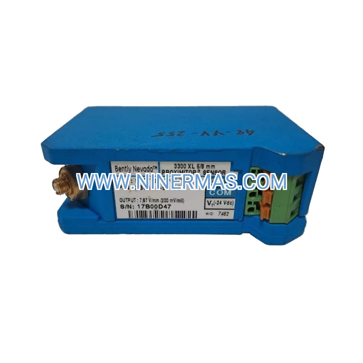
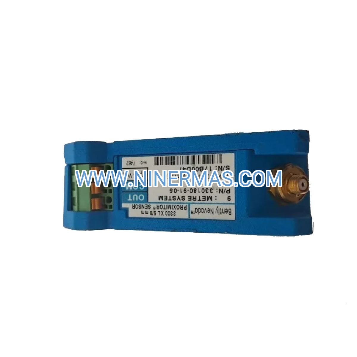
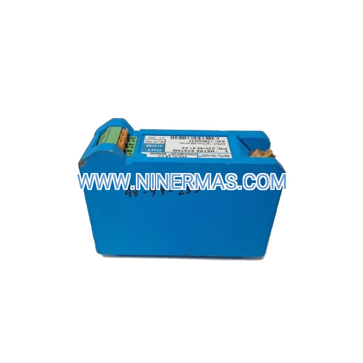
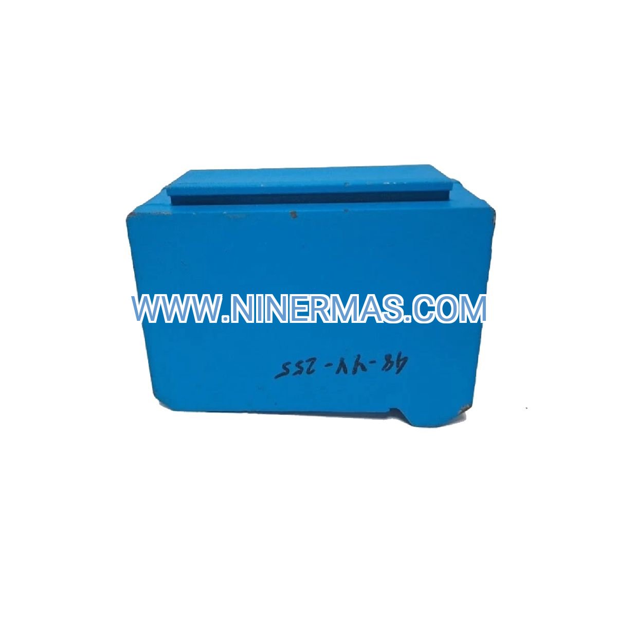
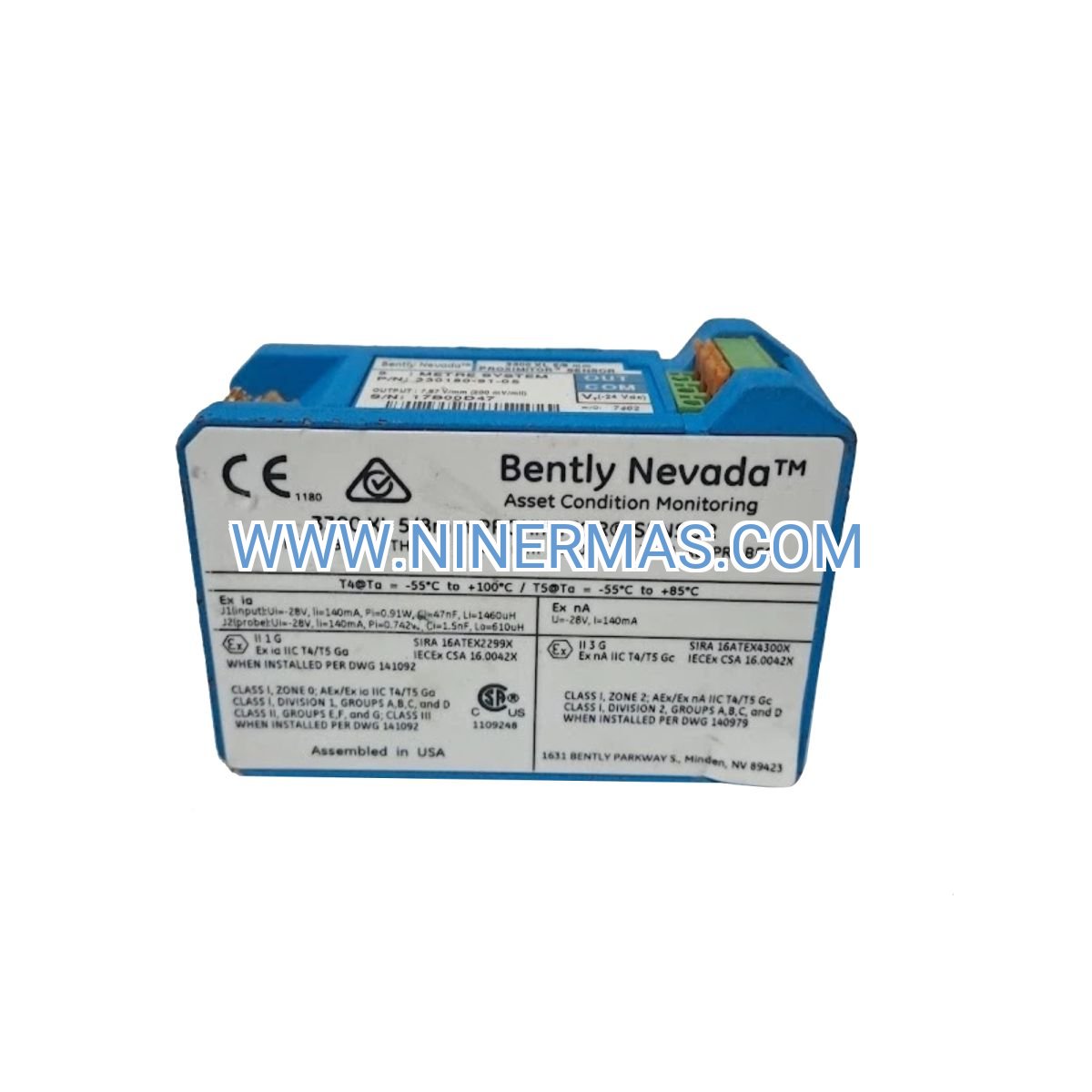
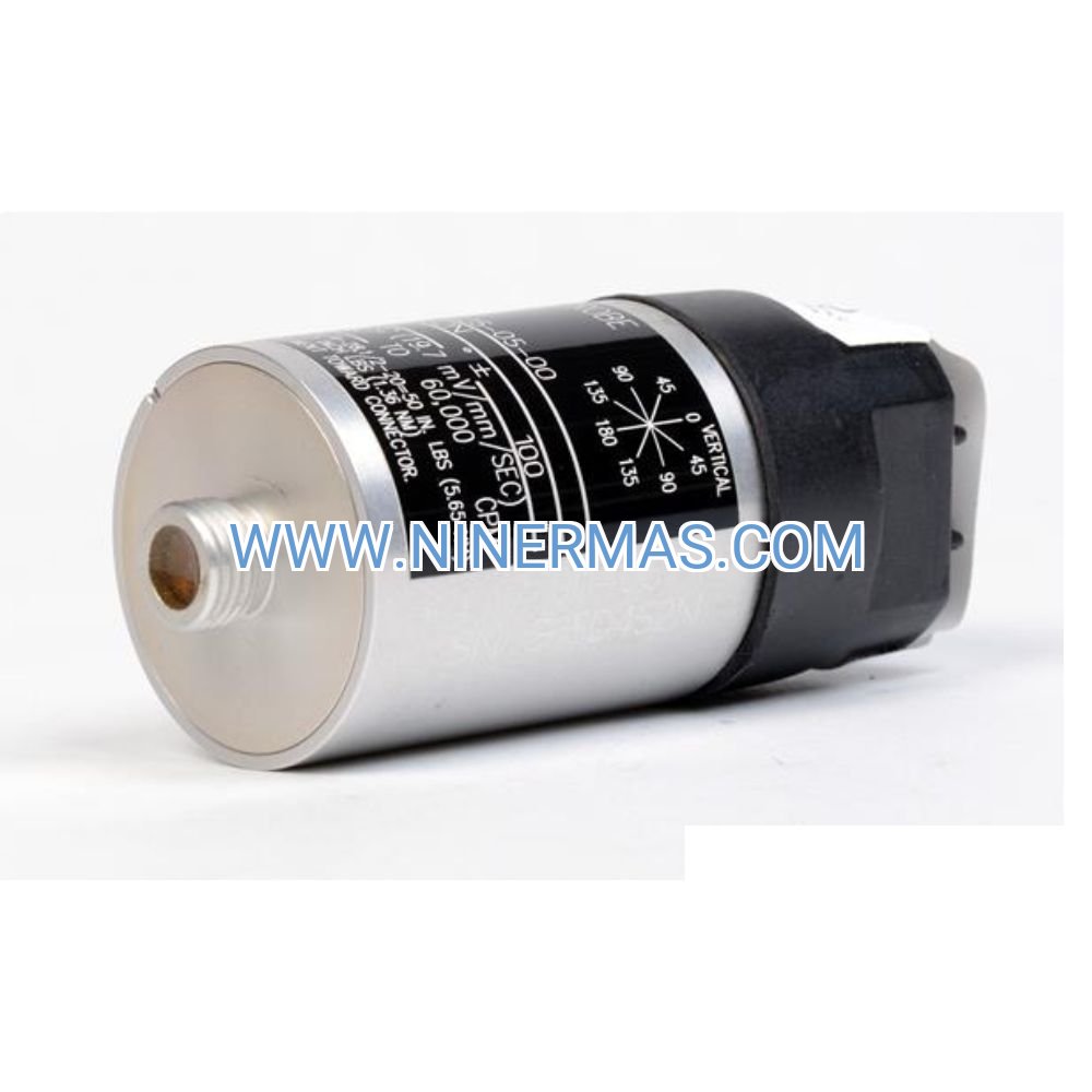
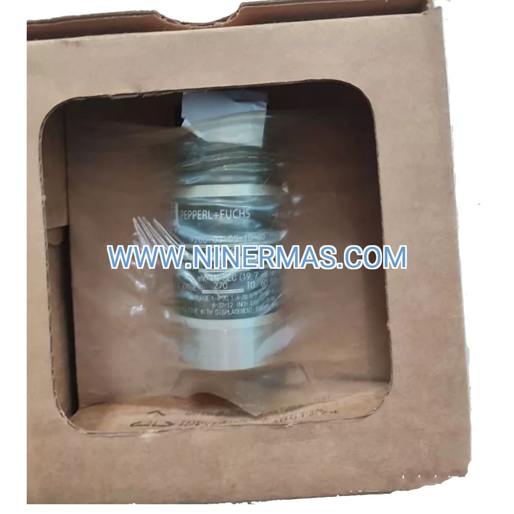
The Bently Nevada 330180-91-EN is an industrial-grade proximity transducer system engineered for continuous shaft displacement and vibration monitoring in critical rotating machinery. Through precision eddy current sensing technology combined with a factory-calibrated 8mm probe and 9-meter DIN-mount cable assembly, this system delivers reliable real-time measurement of radial vibration, axial position, and thrust bearing wear—enabling predictive maintenance strategies that reduce unplanned downtime and extend equipment lifespan.
Designed for high-stakes environments including power generation facilities, petrochemical processing plants, oil & gas compression stations, and heavy industrial manufacturing, the 330180-91-EN addresses critical challenges such as bearing failure detection, rotor eccentricity monitoring, and thermal expansion tracking. Its extended cable length eliminates field splicing requirements while DIN rail compatibility simplifies cabinet integration and reduces installation time.
Built to API 670 fourth edition and ISO 20816 standards with comprehensive factory calibration documentation, this transducer system serves design engineers, maintenance teams, instrumentation contractors, and plant reliability managers. Contact our application engineers to receive customized selection guidance, integration support, and technical specifications tailored to your machinery monitoring requirements.
Core Capabilities & Performance Advantages
Precision Eddy Current Sensing Technology
Utilizes high-frequency electromagnetic field generation to measure gap distance between probe tip and ferromagnetic target surfaces with 200 mV/mil sensitivity, providing micron-level resolution for detecting shaft runout, bearing clearance changes, and rotor dynamic behavior without physical contact or wear.
Factory-Calibrated System Integrity
Each probe-cable-proximitor assembly undergoes multi-point calibration across the full 0.5mm to 2.5mm measurement span with traceable documentation, eliminating field calibration requirements and ensuring measurement accuracy of ±1% across the operating temperature range from -30°C to +100°C.
Extended Cable Configuration Benefits
The integrated 9-meter cable design reduces signal degradation risks associated with extension cables and field terminations, while providing sufficient reach for most turbomachinery installations from bearing housing to control room marshalling panels—cutting installation costs by 20-30% compared to segmented cable systems.
DIN Rail Mounting Flexibility
Proximitor housing features standardized DIN rail clips enabling rapid deployment in control cabinets, junction boxes, and marshalling panels without custom brackets or drilling, supporting both vertical and horizontal orientations while maintaining IP65 environmental protection when properly installed.
Wide Temperature & Environmental Tolerance
Operates reliably in ambient conditions from -30°C to +100°C with probe tip ratings to +177°C, suitable for steam turbine pedestals, gas turbine enclosures, and outdoor compressor stations. Hermetically sealed construction resists moisture ingress, oil mist, and industrial contaminants.
Universal Monitoring System Compatibility
Standard -24 VDC buffered output interfaces directly with 3300 XL monitoring racks, distributed control systems (DCS), programmable logic controllers (PLC), and SCADA platforms. Compatible with 4-20mA converters and voltage isolators for legacy system integration.
Typical Application Scenarios
This proximity transducer system is specifically engineered for installations demanding continuous shaft position monitoring, vibration amplitude tracking, and machinery protection in high-reliability operations:
Power Generation Turbomachinery
Monitors steam turbine journal bearings, thrust positions, and differential expansion in coal-fired, combined-cycle, and nuclear power plants where bearing failures can trigger multi-million dollar outages. Provides early warning of rotor bow, bearing wear, and alignment drift during startup, steady-state operation, and shutdown transients.
Petrochemical & Refining Process Equipment
Tracks centrifugal compressor shaft vibration and axial float in ethylene crackers, catalytic reformers, and fluid catalytic cracking units where process upsets and mechanical failures directly impact production throughput. Enables condition-based maintenance scheduling that reduces forced outages by 40-60% compared to time-based strategies.
Oil & Gas Compression & Pumping Systems
Measures reciprocating and centrifugal compressor bearing clearances in pipeline booster stations, gas processing facilities, and offshore platforms where remote locations make emergency repairs costly and time-consuming. Detects bearing degradation 2-4 weeks before catastrophic failure through trending analysis.
Industrial Manufacturing Critical Drives
Supervises large electric motor bearings, gearbox input/output shafts, and fan assemblies in steel mills, paper machines, cement kilns, and mining conveyors where unplanned downtime disrupts production schedules and supply chain commitments. Integrates with plant-wide asset management systems for predictive analytics.
Technical Specifications & Selection Parameters
To facilitate engineering design and procurement decisions, the following specifications define the 330180-91-EN system capabilities and installation requirements:
| Parameter | Specification |
|---|---|
| Probe Diameter | 8mm (0.315 inch) threaded body |
| Cable Assembly Length | 9.0 meters (29.5 feet) integral construction |
| Connector Type | DIN 43650 European standard (EN designation) |
| Measurement Range | 0.5mm to 2.5mm (20-100 mils) calibrated gap |
| System Sensitivity | 200 mV/mil (7.87 V/mm) typical at 1mm gap |
| Frequency Response | 0 to 10 kHz (-3dB point) |
| Operating Temperature | -30°C to +100°C ambient; probe tip to +177°C |
| Output Signal | -24 VDC buffered (requires proximitor power) |
| Output Impedance | <100 ohms |
| Linearity Error | ±1% of full scale over calibrated range |
| Target Material | Ferromagnetic steel (AISI 4140 calibration standard) |
| Mounting Thread | M8 x 1.0 or 5/16-24 UNF (verify model suffix) |
| Environmental Rating | IP65 when properly installed with mating connector |
| Standards Compliance | API 670 4th Edition, ISO 20816, CE marked |
| System Weight | Approximately 0.7 kg (1.5 lbs) complete assembly |
Selection Guidance for Engineers
When specifying proximity transducer systems, consider the following application parameters: maximum shaft vibration amplitude (select measurement range with 2:1 safety margin), installation gap distance (maintain 1.0-1.5mm nominal for optimal linearity), cable routing distance from bearing housing to monitoring equipment (9m standard; contact for custom lengths), mounting accessibility (threaded body requires 50mm clearance for installation tool), target shaft material and surface finish (4140 steel with 32 Ra or better recommended), and ambient temperature extremes including steam/oil exposure.
For complex installations involving multiple measurement planes, non-standard shaft materials, or integration with third-party monitoring systems, provide our application engineers with machinery drawings, vibration specifications, and environmental conditions. We will recommend optimal probe positioning, cable routing strategies, and signal conditioning requirements to ensure measurement accuracy and system reliability.
Advanced Integration Features
Multi-Channel Monitoring Architectures
Supports radial X-Y vibration pairs, dual axial thrust monitoring, and differential expansion measurements when deployed with matching transducers. Compatible with 3300 XL 8-channel and 16-channel rack systems for centralized turbomachinery protection and trending.
Digital Communication Readiness
While providing traditional analog output, the system interfaces with Bently Nevada ADAPT software and System 1 condition monitoring platforms through compatible proximitor modules, enabling remote diagnostics, automated alarm management, and cloud-based analytics integration.
Hazardous Area Deployment
When paired with intrinsically safe barriers and certified proximitor housings, the 330180-91-EN probe assembly qualifies for Class I Division 2 and ATEX Zone 2 installations in oil & gas and chemical processing environments (consult factory for certification documentation).
Delivery, Quality Assurance & Technical Support
Lead Times & Availability
Standard 330180-91-EN configurations typically ship within 3-5 business days from regional distribution centers. Custom cable lengths, special connector types, or high-temperature probe variants require 2-3 weeks manufacturing lead time. Expedited processing available for emergency outage support with 24-48 hour turnaround (subject to stock availability and destination).
Warranty & Service Coverage
All transducer systems include a comprehensive 12-month warranty covering manufacturing defects, calibration drift beyond published specifications, and component failures under normal operating conditions. Warranty protection begins from shipment date and includes no-cost replacement or repair with return freight prepaid. Extended warranty programs available for critical applications requiring 3-year or 5-year coverage.
Installation & Commissioning Assistance
Technical support includes remote guidance for probe installation, gap voltage verification, and signal quality validation via phone and video conferencing. On-site commissioning services available in major industrial regions for multi-transducer installations, system integration projects, and operator training programs (quoted separately based on location and scope).
Documentation & Certification Package
Each system ships with complete technical documentation including: dimensional installation drawings with mounting torque specifications, factory calibration curves with serial number traceability, electrical connection diagrams for proximitor wiring, troubleshooting flowcharts for common installation issues, and material certifications (MTR) upon request. Digital documentation library accessible through customer portal for replacement reference.
Frequently Asked Questions
Q: How does the 330180-91-EN proximity transducer system measure vibration without physical contact?
A: The system generates a high-frequency electromagnetic field from the probe tip. When positioned near a ferromagnetic shaft surface, eddy currents induced in the target material create a back-EMF that varies with gap distance. The proximitor electronics convert this impedance change into a proportional DC voltage output representing shaft position. As the shaft vibrates, the gap oscillates, producing an AC signal superimposed on the DC gap voltage—this AC component represents vibration amplitude and frequency.
Q: What differentiates the -91-EN model designation from other 330180 series variants?
A: The model suffix indicates specific configuration details: "91" specifies a 9-meter integral cable length (versus 5m for -50 or 1m for -10 models), while "EN" designates a European DIN 43650 connector standard rather than Bendix or MIL-spec connectors used in North American configurations. This combination optimizes the system for European industrial installations requiring extended cable runs without field splicing, reducing installation costs and potential failure points.
Q: Can this proximity sensor monitor non-ferrous materials like stainless steel, aluminum, or titanium shafts?
A: No. Eddy current proximity transducers require ferromagnetic target materials (carbon steel, alloy steel, cast iron) to generate sufficient signal strength. Austenitic stainless steels (300 series), aluminum, titanium, and brass produce inadequate response. For non-ferrous shaft monitoring, consider capacitive displacement sensors or laser-based optical systems. Consult our application engineers to identify appropriate sensing technologies for your specific shaft material and measurement requirements.
Q: Is field recalibration necessary after installing the transducer system on machinery?
A: No. The 330180-91-EN ships as a factory-calibrated matched set (probe + cable + proximitor) with calibration valid for the complete assembly. Field calibration is only required if: (1) components are separated and remixed with different serial numbers, (2) the target shaft material differs significantly from AISI 4140 calibration standard, or (3) calibration verification is mandated by plant quality procedures. For standard installations on carbon steel shafts, simply verify gap voltage falls within the calibrated range (typically -8 to -20 VDC at 1-2mm gap).
Q: What is the maximum number of proximity transducers that can connect to a single monitoring system?
A: This depends on your monitoring platform architecture. A standard 3300 XL 8-channel rack accommodates eight transducers (four radial X-Y pairs or eight single-plane measurements). The 3300 XL 16-channel rack doubles this capacity. For larger turbine-generator sets requiring 20+ measurement points, multiple racks network together via Modbus or Ethernet protocols. Distributed control systems (DCS) and SCADA platforms typically accept 16-32 analog inputs per I/O card. Contact us with your machinery configuration and monitoring objectives for system architecture recommendations.
Q: How do I select the correct installation gap distance for optimal measurement accuracy?
A: For the 330180-91-EN with 0.5-2.5mm calibrated range, install the probe to achieve a 1.0-1.5mm nominal gap (corresponding to approximately -10 to -12 VDC gap voltage). This positions the operating point in the linear region of the calibration curve, providing maximum dynamic range for vibration measurement while maintaining adequate clearance to prevent probe-to-shaft contact during transient events. Avoid gaps below 0.7mm (risk of contact) or above 2.0mm (reduced sensitivity and linearity). Use a feeler gauge or gap voltage measurement during installation to verify proper positioning.
Q: Does the system support remote monitoring and predictive analytics integration?
A: Yes, when interfaced with compatible monitoring platforms. The analog output connects to Bently Nevada System 1 software, OSI-PI historians, or third-party condition monitoring systems that provide remote access, automated alarming, trend analysis, and machine learning-based anomaly detection. For IIoT integration, pair the transducer with edge computing gateways supporting OPC-UA or MQTT protocols to stream vibration data to cloud analytics platforms. We offer integration consulting services to design data acquisition architectures meeting your connectivity and cybersecurity requirements.
Request Technical Consultation & Custom Quotation
To receive detailed application engineering support, system selection guidance, or project-specific pricing, please provide the following information to our technical sales team:
- Project Overview: Facility type, machinery description, monitoring objectives
- Equipment Details: Rotating machinery type (turbine/compressor/motor), shaft diameter, bearing configuration, operating speed range
- Measurement Requirements: Number of measurement planes, vibration amplitude expectations, axial float monitoring needs
- Installation Constraints: Cable routing distance, mounting accessibility, ambient temperature range, hazardous area classification
- System Integration: Existing monitoring platform (DCS/SCADA/standalone), communication protocol requirements, alarm setpoint preferences
- Timeline & Quantity: Project schedule, number of transducer systems required, delivery location
Our application engineers will respond within one business day with customized recommendations including transducer positioning strategies, cable routing best practices, signal conditioning requirements, and complete bill of materials with pricing. For urgent outage support or emergency replacements, contact our 24/7 technical hotline for expedited processing.
© 2026 NINERMAS COMPANY LIMITED. All rights reserved.
Original Source: https://ninermas.com
Contact: sale@ninermas.com | +0086 187 5021 5667
PDF Specification
Download PDF file here:
Click to Download PDF

Contact Info
-
Address:22 / F, South Wo Hang building, 148 Wing Lok Street, Sheung Wan, Western District, Hong Kong
-
Phone:+8618750215667
-
Email: