Description
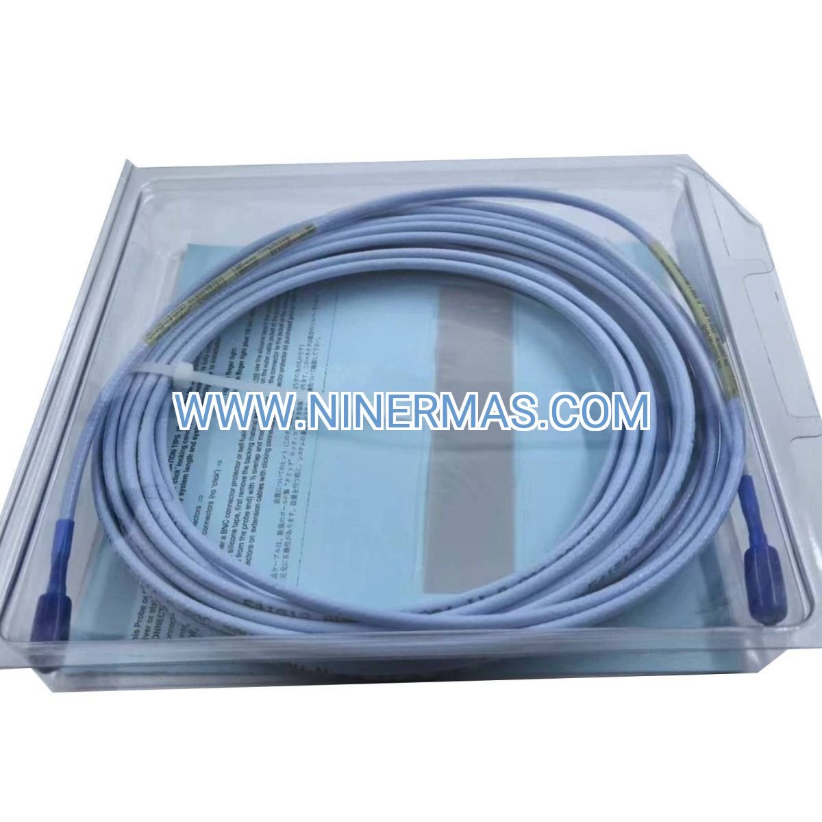
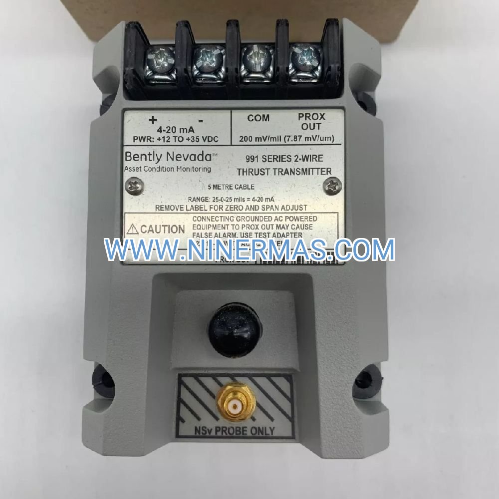
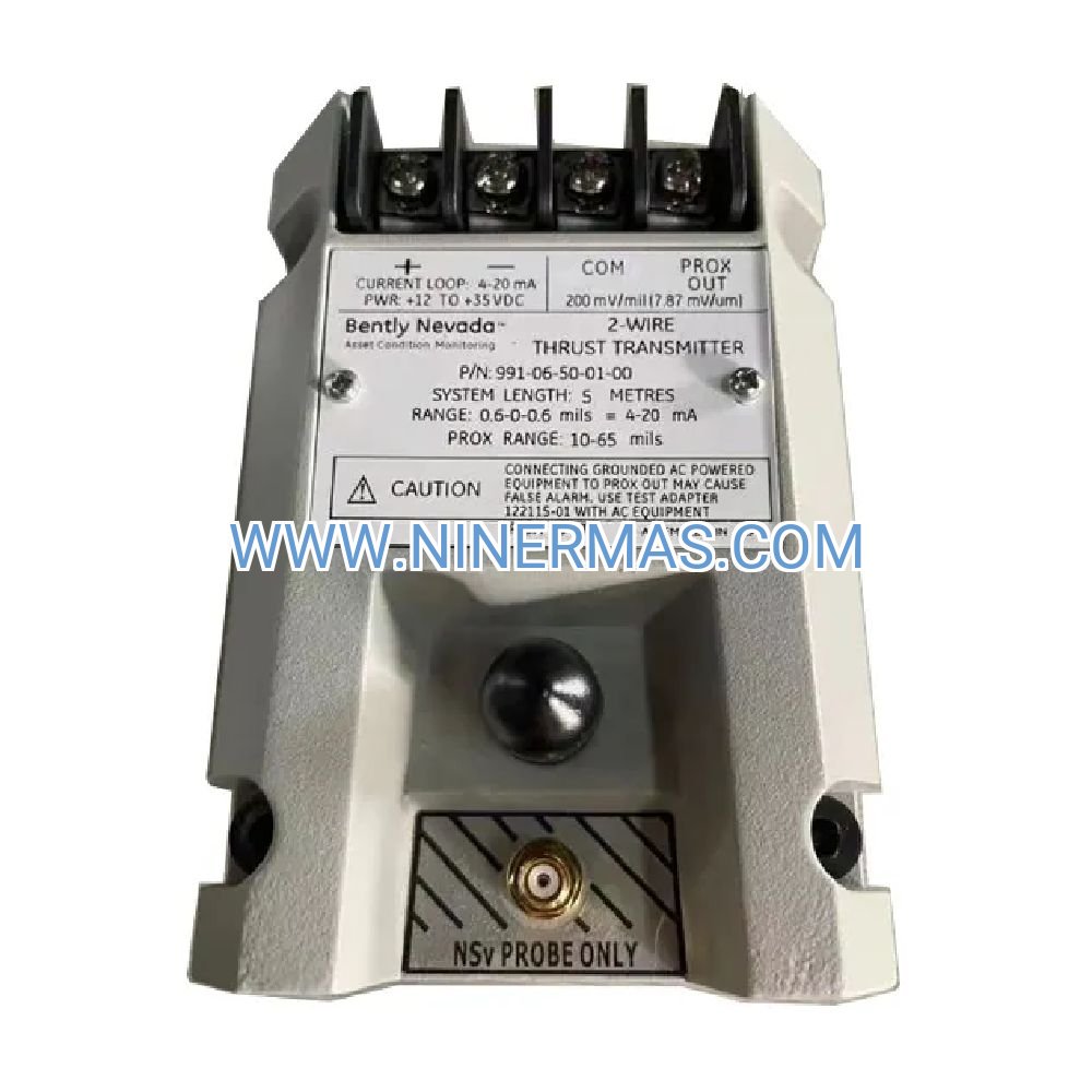
Bently Nevada 330140-08-15-12-00-00 | Industrial-Grade 8mm Proximity Transducer for Critical Machinery Protection
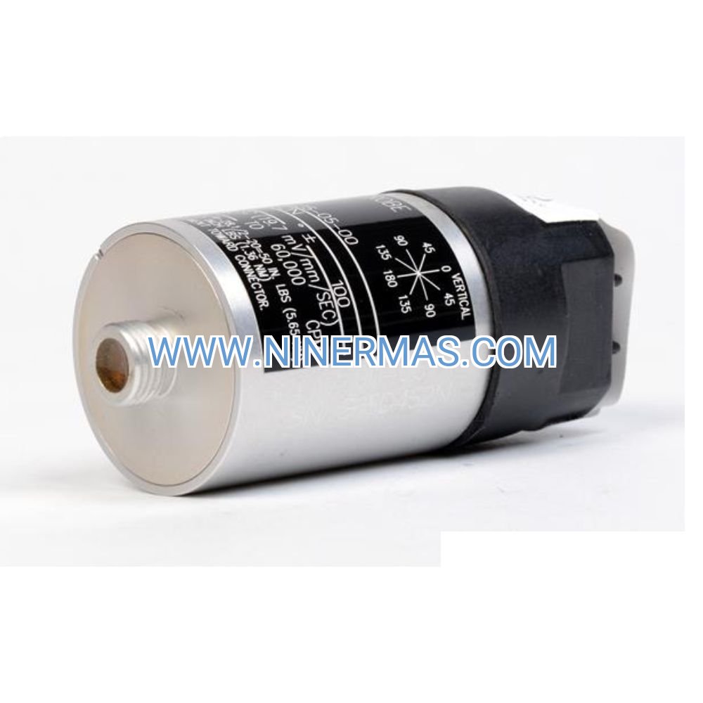
The Bently Nevada 330140-08-15-12-00-00 is a precision-engineered 8mm proximity transducer designed for continuous vibration and displacement monitoring in mission-critical rotating machinery. Utilizing eddy current sensing technology, this transducer delivers real-time shaft position data to prevent catastrophic failures in turbines, compressors, pumps, and high-speed motors across power generation, petrochemical, and heavy industrial facilities.
Ideal for design engineers, maintenance teams, and system integrators who require reliable condition monitoring solutions. This 3300 XL series sensor addresses common challenges including unplanned downtime, bearing degradation, shaft misalignment, and rotor instability—helping facilities maintain operational continuity while reducing maintenance costs by up to 40% through predictive analytics.
Built with aerospace-grade materials and IP67-rated construction, the 330140-08-15-12-00-00 withstands extreme temperatures (-40°C to +105°C), electromagnetic interference, and harsh chemical environments. Seamlessly integrates with existing Bently Nevada 3300 XL monitoring infrastructure and third-party SCADA systems via industry-standard protocols. Contact our application engineers for customized selection guidance, technical drawings, and competitive quotations.
Core Features & Technical Advantages
- High-Precision Eddy Current Sensing
Non-contact measurement technology with 8mm probe diameter provides exceptional sensitivity for detecting micro-level shaft displacement (±0.5 μm resolution), enabling early identification of bearing wear, thermal growth, and dynamic imbalance before they escalate into costly failures. - Wide Frequency Response for Dynamic Monitoring
DC to 10 kHz bandwidth (-3dB) captures both slow-roll baseline data and high-frequency vibration signatures, supporting comprehensive analysis of subsynchronous, synchronous, and supersynchronous phenomena in variable-speed machinery. - Extended Temperature Range & Environmental Durability
Operates reliably from -40°C to +105°C with hermetically sealed construction, making it suitable for arctic offshore platforms, desert refineries, and high-temperature steam turbine applications where conventional sensors fail. - Flexible Installation & System Compatibility
Standard M18×1.5 thread mounting with adjustable gap settings (1.0–2.0mm optimal range). Compatible with 3300 XL Proximitor sensors, 3500 rack monitoring systems, and legacy 3300 NSv platforms—minimizing retrofit complexity and capital expenditure. - Comprehensive Protection & Diagnostics
Built-in cable integrity monitoring, temperature compensation, and EMI/RFI shielding ensure signal accuracy in electrically noisy environments. Self-diagnostic capabilities alert operators to sensor degradation or installation issues before measurement errors occur. - Proven Reliability in Critical Applications
MTBF exceeding 200,000 hours in continuous operation, backed by ISO 9001-certified manufacturing and compliance with API 670 machinery protection standards. Trusted by Fortune 500 companies for protecting assets valued at millions of dollars.
Typical Application Scenarios
The Bently Nevada 330140-08-15-12-00-00 proximity transducer serves industries where machinery reliability directly impacts safety, production output, and profitability:
- Steam & Gas Turbine Monitoring
Measures axial position, differential expansion, and radial vibration in power generation turbines operating at 3,000–3,600 RPM. Prevents blade rubs, thrust bearing failures, and catastrophic rotor seizures that can cause multi-million dollar outages. - Centrifugal Compressor Protection Systems
Monitors shaft displacement and casing vibration in multi-stage compressors handling corrosive gases or high-pressure refrigerants. Detects surge conditions, seal degradation, and impeller imbalance in real-time, triggering automated shutdowns when thresholds are exceeded. - Critical Pump Bearing Health Monitoring
Tracks radial shaft motion in boiler feed pumps, pipeline transfer pumps, and reactor coolant pumps. Early detection of cavitation, misalignment, and bearing wear extends mean time between overhauls (MTBO) by 30–50% while reducing unscheduled maintenance events. - High-Speed Motor & Generator Condition Monitoring
Provides continuous surveillance of rotor eccentricity and magnetic center position in synchronous motors and generators rated above 1 MW. Supports predictive maintenance programs compliant with IEEE 841 and NEMA MG-1 standards. - Petrochemical & Refinery Rotating Equipment
Deployed across hydrocracker compressors, catalytic cracker blowers, and crude distillation pumps where process uptime directly correlates to revenue. Integrates with DCS and asset management platforms for enterprise-wide condition monitoring. - Offshore Oil & Gas Production Facilities
Withstands saltwater corrosion, vibration from wave action, and extreme temperature swings on FPSO vessels and fixed platforms. Monitors gas compression trains, seawater injection pumps, and power generation turbines in unmanned installations.
Technical Specifications & Selection Parameters
To ensure optimal performance and compatibility with your machinery protection system, review the following specifications. Our engineering team can assist with gap calibration, cable routing, and system integration planning.
| Parameter | Specification | Notes |
|---|---|---|
| Model Number | 330140-08-15-12-00-00 | Factory-configured, non-modifiable |
| Probe Diameter | 8mm (0.315 inch) | Requires M18×1.5 mounting hole |
| Series Compatibility | 3300 XL, 3500 Series | Verify proximitor model compatibility |
| Frequency Response | DC to 10 kHz (-3dB) | Suitable for variable-speed machinery |
| Operating Temperature | -40°C to +105°C (-40°F to +221°F) | Consult for extreme environments |
| Linear Range | 1.0mm to 2.0mm (40–80 mils) | Gap from ferromagnetic target |
| Output Signal | -2 to -18 Vdc (linear) | Requires compatible proximitor |
| Cable Length | Standard 5m / Custom available | Extension cables affect calibration |
| Target Material | 4140 steel, 416 SS (ferromagnetic) | Avoid aluminum or non-magnetic alloys |
| Protection Rating | IP67 (when properly installed) | Hermetically sealed construction |
| Compliance Standards | API 670, ISO 10816, ISO 7919 | Meets global machinery standards |
| Weight | Approx. 0.2 kg (0.44 lbs) | Excluding cable assembly |
Selection Guidance & Application Engineering
Proper transducer selection requires analysis of multiple factors to ensure measurement accuracy and long-term reliability. When specifying the 330140-08-15-12-00-00, consider:
- Shaft Material & Surface Finish: Target surface must be ferromagnetic with Ra ≤ 3.2 μm (125 μin) for optimal linearity. Non-magnetic shafts require ferromagnetic sleeves or alternative sensing technologies.
- Installation Gap & Mechanical Runout: Maintain 1.5mm nominal gap with ±0.5mm tolerance. Total indicated runout (TIR) should not exceed 50% of linear range to prevent signal clipping during operation.
- Environmental Conditions: Verify ambient temperature, vibration levels, and chemical exposure. High-temperature applications (>85°C) may require heat shields or remote mounting configurations.
- System Architecture: Confirm proximitor model, cable routing distance, and monitoring system input requirements. Impedance matching and grounding practices significantly impact signal integrity.
- Regulatory & Safety Requirements: Ensure compliance with local electrical codes, hazardous area classifications (ATEX, IECEx), and machinery safety standards (ISO 13849, IEC 61508).
Need assistance with selection? Provide our engineering team with: machinery type, operating speed range, shaft diameter, mounting constraints, ambient conditions, and monitoring system details. We'll recommend the optimal configuration and provide certified calibration data, installation drawings, and commissioning support.
Advanced Integration & Monitoring Capabilities
The 330140-08-15-12-00-00 transducer serves as a foundational element in comprehensive machinery health monitoring architectures:
- Multi-Channel Monitoring Systems: Deploy in XY probe pairs for radial vibration analysis, or combine with axial position sensors for complete rotor dynamics assessment. Supports orbit plots, Bode diagrams, and polar plots for root cause diagnostics.
- Predictive Maintenance Integration: Streams continuous data to CMMS platforms (SAP PM, Maximo, eMaint) and condition monitoring software (System 1, AMS Suite, PROGNOST). Enables trend analysis, alarm management, and automated work order generation.
- IIoT & Cloud Connectivity: Interfaces with edge gateways and industrial IoT platforms for remote monitoring, machine learning-based anomaly detection, and fleet-wide performance benchmarking across distributed facilities.
- Safety Instrumented Systems (SIS): Certified for use in SIL 2-rated machinery protection systems per IEC 61508. Provides redundant shutdown signals when vibration or position exceeds critical thresholds, preventing equipment damage and personnel injury.
Delivery, Commissioning & Technical Support
Lead Times & Logistics: Standard factory-sealed units ship within 3–5 business days from regional distribution centers in North America, Europe, and Asia-Pacific. Custom cable lengths or special configurations require 10–15 business days. Expedited shipping available for critical outage situations.
Quality Assurance: Every transducer undergoes 100% factory testing including gap calibration, frequency response verification, and environmental stress screening. Supplied with individual calibration certificate traceable to NIST/PTB standards and serialized quality documentation.
Warranty Coverage: Backed by a comprehensive 12-month manufacturer warranty covering material defects, workmanship issues, and performance deviations from published specifications. Extended warranty programs available for critical applications requiring 3–5 year coverage.
Installation & Commissioning Services: Our field service engineers provide on-site installation supervision, gap setting verification, system integration testing, and operator training. Remote commissioning support available via video consultation for standard installations.
Technical Documentation Package: Includes detailed installation manual, electrical schematics, mechanical drawings (DWG/PDF), calibration curves, material certifications, and recommended spare parts list. Digital asset library accessible 24/7 through customer portal.
Ongoing Support: Access to application engineers with 15+ years of rotating machinery expertise. Troubleshooting assistance, retrofit planning, system upgrades, and training programs available. Emergency support hotline for critical production environments.
Frequently Asked Questions (FAQ)
Q: What is the recommended installation gap for the 330140-08-15-12-00-00 proximity transducer?
A: The optimal gap range is 1.0mm to 2.0mm (40 to 80 mils) from the ferromagnetic target surface. We recommend setting the nominal gap at 1.5mm to provide equal headroom for shaft growth and runout. Use precision feeler gauges or non-contact gap measurement tools during installation to ensure accuracy within ±0.1mm.
Q: Can this 8mm proximity transducer be used with non-Bently Nevada monitoring systems?
A: Yes, provided the monitoring system uses compatible 3300 XL Proximitor sensors or equivalent eddy current signal conditioners with matching electrical characteristics (-24 Vdc supply, 7.87 V/mm sensitivity). Verify input impedance, frequency response, and calibration factors before integration. Contact our technical team for third-party system compatibility verification.
Q: What target materials provide the best measurement accuracy?
A: Ferromagnetic materials such as AISI 4140 steel, 416 stainless steel, and similar iron-based alloys deliver optimal performance. Target surface should have magnetic permeability >100 and electrical conductivity >1 MS/m. Avoid aluminum, brass, titanium, or austenitic stainless steels (300 series) as they produce non-linear or unstable signals.
Q: How do I verify proper transducer operation after installation?
A: Perform a three-step validation: (1) Measure static gap using calibrated feeler gauges and confirm output voltage matches calibration curve (typically -10 Vdc at 1.5mm gap). (2) Manually vary gap across linear range and verify proportional voltage change. (3) During machine startup, observe dynamic signal on oscilloscope to confirm clean waveform without noise, clipping, or dropouts.
Q: What is the maximum cable extension length without signal degradation?
A: Standard 5-meter integral cable can be extended up to 9 meters total using approved extension cables (Bently Nevada part 330130 series). Longer runs require re-calibration to compensate for cable capacitance effects. For distances exceeding 9 meters, consider proximitor relocation or signal conditioning at the transducer mounting point.
Q: Is the 330140-08-15-12-00-00 suitable for hazardous area installations?
A: The transducer itself is intrinsically safe when paired with appropriately certified proximitor sensors and barriers. For Class I Division 1 or ATEX Zone 1 applications, ensure complete system certification including transducer, proximitor, cabling, and monitoring equipment. Consult factory for application-specific certifications and installation drawings.
Q: What maintenance is required for proximity transducers in continuous service?
A: Proximity transducers are maintenance-free solid-state devices with no moving parts. Recommended practices include: (1) Annual gap verification during scheduled outages. (2) Visual inspection of cable integrity and connector seals. (3) Periodic calibration verification using portable gap measurement tools. (4) Monitoring system self-diagnostics for cable faults or sensor degradation alerts.
Request Technical Consultation & Quotation
Our application engineering team is ready to assist with system design, product selection, and project execution. To receive a detailed technical proposal and competitive pricing, please provide:
- Project Overview: Facility type, machinery description, monitoring objectives
- Machinery Details: Equipment type (turbine/compressor/pump), operating speed range, shaft diameter, bearing configuration
- Measurement Requirements: Radial vibration, axial position, differential expansion, or multi-parameter monitoring
- Environmental Conditions: Ambient temperature range, hazardous area classification, vibration/shock levels
- System Architecture: Existing monitoring infrastructure, communication protocols, integration requirements
- Quantity & Timeline: Number of measurement points, project schedule, budget constraints
Submit your inquiry via email to sale@ninermas.com or call +0086 187 5021 5667 to speak directly with a vibration monitoring specialist. We typically respond within 4 business hours with preliminary recommendations and can schedule virtual or on-site technical reviews for complex projects.
© 2026 NINERMAS COMPANY LIMITED. All rights reserved.
Original Source: https://ninermas.com
Contact: sale@ninermas.com | +0086 187 5021 5667

Contact Info
-
Address:22 / F, South Wo Hang building, 148 Wing Lok Street, Sheung Wan, Western District, Hong Kong
-
Phone:+8618750215667
-
Email: