Description
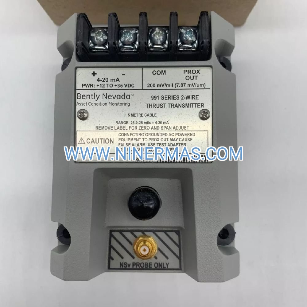
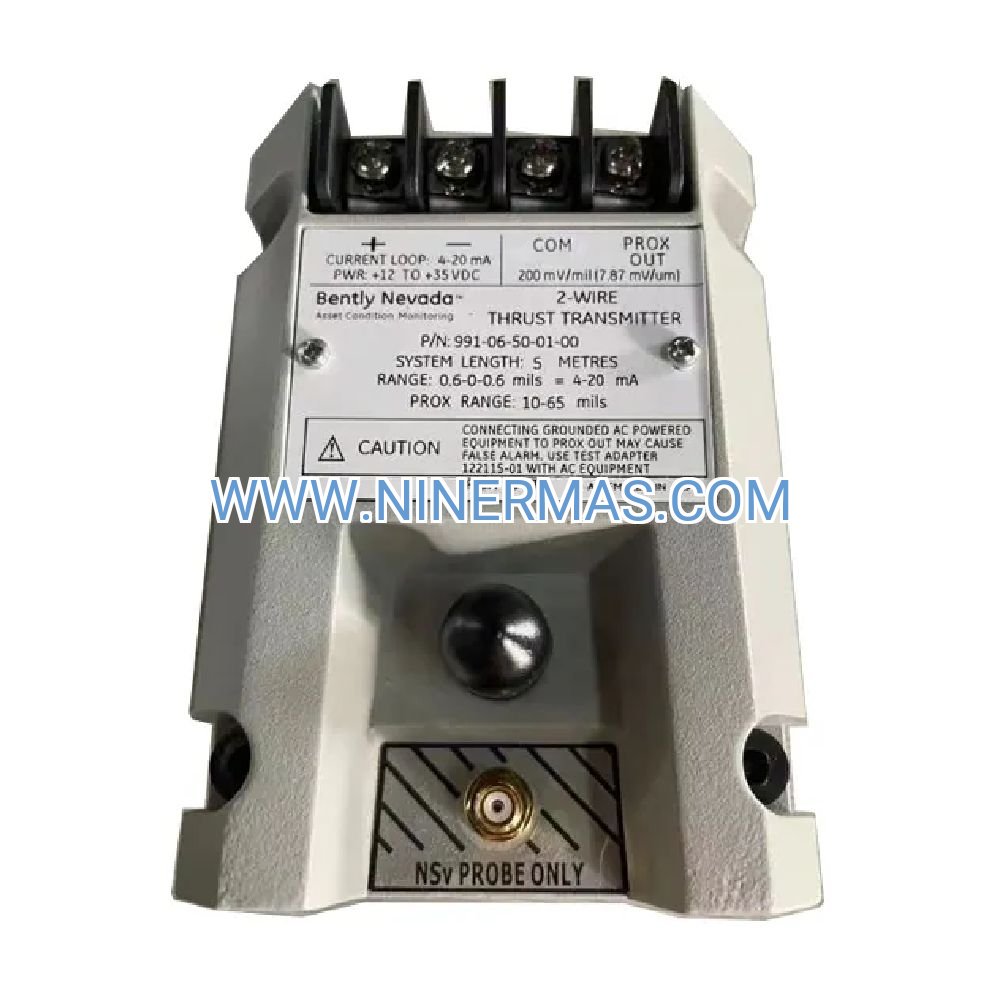
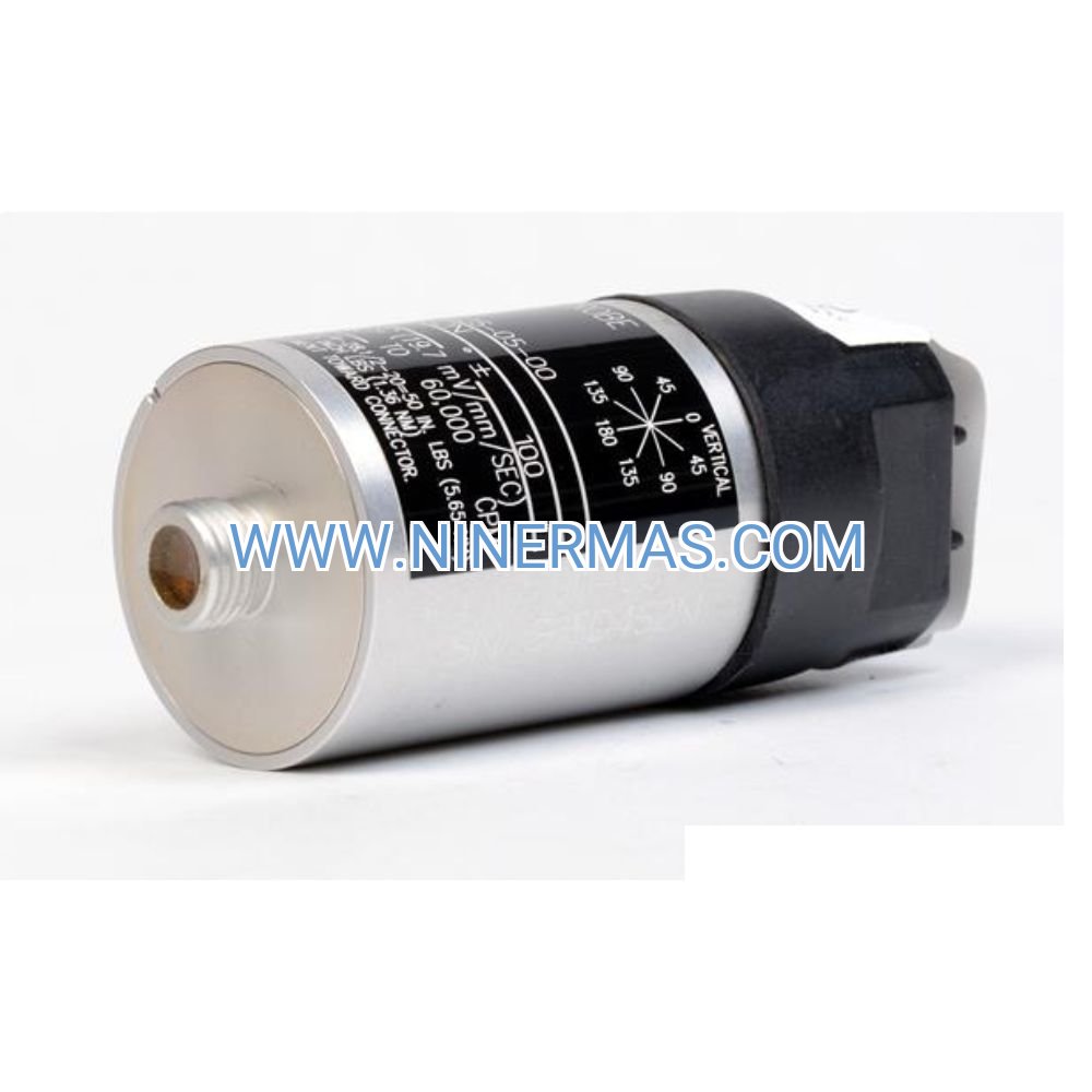
Bently Nevada 330140-08-10-11-05-00 8mm Proximity Transducer (Industrial Vibration Monitoring System)
The Bently Nevada 330140-08-10-11-05-00 is an industrial-grade proximity transducer designed for non-contact displacement and vibration measurement in critical rotating machinery. Leveraging the proven 3300 XL platform architecture, this 8mm probe delivers precise shaft position tracking and dynamic vibration data through eddy current sensing technology, enabling real-time condition monitoring and predictive maintenance across turbomachinery installations in power generation, petrochemical processing, and heavy industrial environments.
Suitable for steam turbines, gas compressors, centrifugal pumps, large motors, and hydro-turbine applications, this transducer addresses common operational challenges including bearing wear detection, rotor eccentricity tracking, thrust position monitoring, and unbalance identification. By providing continuous displacement feedback with ±1% linearity over the calibrated range, the system helps prevent catastrophic failures, reduces unplanned downtime, and extends equipment service life through early fault detection.
Through standardized mechanical interfaces and field-proven reliability, the 330140-08-10-11-05-00 integrates seamlessly with existing 3300 XL proximitor modules and distributed control systems. Available with comprehensive technical documentation and application engineering support, this transducer suits design engineers, instrumentation contractors, plant maintenance teams, and OEM integrators requiring API 670-compliant vibration monitoring solutions. Contact our application engineers for system configuration recommendations and project-specific quotations.
Core Features & Performance Advantages
Precision Eddy Current Sensing Technology
Utilizes high-frequency oscillator circuits to generate electromagnetic fields that interact with conductive target surfaces, producing linear voltage output proportional to gap distance. This non-contact measurement principle eliminates mechanical wear and enables continuous monitoring without affecting rotor dynamics or introducing parasitic loads.
Wide Frequency Response for Comprehensive Monitoring
Captures displacement signals from DC (static position) to 10 kHz (-3dB point), covering slow-roll baseline measurements, synchronous vibration components, subsynchronous instabilities, and high-frequency bearing defect signatures. This bandwidth supports both protection logic and diagnostic analysis across all operating speed ranges.
Rugged Stainless Steel Construction
Manufactured from corrosion-resistant 300-series stainless steel with hermetically sealed electronics, providing long-term stability in environments with temperature cycling (-40°C to +105°C), chemical exposure, moisture ingress, and mechanical vibration. Field-proven reliability exceeds 100,000 operating hours in continuous service applications.
Standardized 3300 XL System Compatibility
Direct plug-and-play integration with all 3300 XL proximitor modules (330180, 330780 series) and legacy 3300 NSv systems, ensuring backward compatibility during retrofit projects and forward migration paths for monitoring system upgrades. Maintains -200 mV/mil sensitivity standard across the installed base.
Field-Replaceable Modular Design
Threaded mounting configuration with integral armored cable enables rapid probe replacement during planned outages without specialized tooling or hot work permits. Typical swap-out time under 30 minutes minimizes maintenance window requirements and supports just-in-time spare parts strategies.
API 670 & ISO 20816 Compliance
Meets or exceeds requirements specified in API Standard 670 (Machinery Protection Systems) 4th Edition and ISO 20816 (Mechanical Vibration - Measurement and Evaluation), ensuring acceptance by engineering firms, insurance underwriters, and regulatory authorities for critical machinery installations.
Typical Application Scenarios
This proximity transducer addresses vibration monitoring requirements in applications where shaft displacement data drives protection decisions and maintenance planning:
Steam Turbine Generator Sets
Radial vibration measurement at journal bearings, thrust position monitoring at active thrust collars, and differential expansion tracking between casing and rotor assemblies. Supports trip logic for excessive vibration, thrust failure, and thermal growth anomalies in utility-scale and industrial cogeneration units from 5 MW to 1000+ MW capacity.
Gas Turbine Compressor Trains
Multi-stage compressor vibration profiling, surge detection through shaft motion analysis, and rotor eccentricity monitoring in aero-derivative frames (LM2500, LM6000) and heavy-duty industrial gas turbines (Frame 6, Frame 7, Frame 9). Enables condition-based maintenance and performance optimization in pipeline compression and LNG liquefaction service.
Centrifugal Process Compressors
Bearing clearance verification, seal rub detection, and aerodynamic instability identification in API 617 barrel-type and horizontally-split compressors handling process gas, refrigeration, air separation, and petrochemical applications. Supports online balancing and alignment verification during commissioning and after maintenance interventions.
Large Synchronous Motors & Generators
Rotor position tracking and bearing wear trending in motors above 1 MW and generators from 10 MVA to 500+ MVA ratings. Detects electrical unbalance, mechanical looseness, foundation issues, and coupling misalignment in critical drive applications including boiler feed pumps, induced draft fans, and mill drives.
Hydroelectric Turbine-Generator Units
Guide bearing displacement monitoring and thrust collar position measurement in Francis, Kaplan, and Pelton wheel configurations. Addresses hydraulic unbalance, cavitation-induced vibration, and wicket gate wear in run-of-river, reservoir, and pumped-storage installations from 5 MW to 700+ MW unit capacity.
Technical Parameters & Selection Guide
To facilitate engineering design and procurement, the following specifications define the operational envelope and mechanical interface requirements:
| Parameter | Specification | Notes |
|---|---|---|
| Model Number | 330140-08-10-11-05-00 | Factory configuration code |
| Probe Diameter | 8mm (0.315") | Suitable for standard mounting holes |
| Thread Specification | 5/8-18 UNF-2A | 10mm effective thread length |
| Linear Range | 1.0–2.0mm (40–80 mils) | ±1% linearity specification |
| Frequency Response | DC to 10 kHz (-3dB) | Covers all machinery fault frequencies |
| Operating Temperature | -40°C to +105°C | Continuous rating without derating |
| Housing Material | 300-series stainless steel | Corrosion-resistant construction |
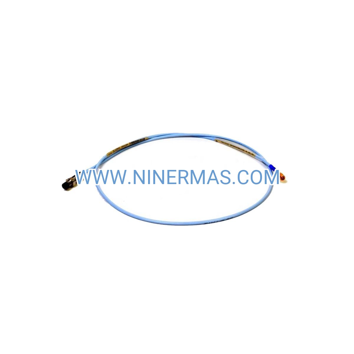
| Cable Type | Integral armored coaxial | BNC connector termination |
| Target Material | Ferromagnetic (4140 steel typical) | Minimum 75mm (3") diameter |
| Surface Finish | 32 microinch Ra or better | Minimizes electrical runout |
| Compliance Standards | API 670 4th Ed., ISO 20816 | Industry-accepted certifications |
Selection Considerations
When specifying proximity transducers for your application, evaluate the following project parameters: maximum shaft displacement during transient events (startup, shutdown, trip conditions), operating speed range and corresponding vibration frequencies, ambient temperature envelope including solar radiation effects, installation space constraints (radial clearance, axial depth), target material composition and surface condition, proximitor module compatibility with existing monitoring infrastructure, and hazardous area classification requirements. For complex installations involving multiple measurement planes, non-standard mounting geometries, or extreme environmental conditions, submit application worksheets including machinery drawings, operating profiles, and protection philosophy documentation to our application engineering team for validated system recommendations.
Extended Capabilities & System Integration
Hazardous Area Deployment
When paired with certified intrinsically safe barriers (MTL, Pepperl+Fuchs, or equivalent) and approved proximitor modules, this transducer supports installations in Class I Division 2, Zone 2, ATEX Zone 2 (Group IIC), and IECEx environments. Consult entity parameter documentation and installation drawings to ensure barrier selection maintains system certification and does not compromise measurement bandwidth or sensitivity.
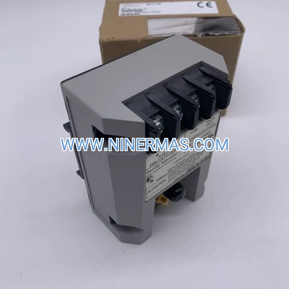
Digital Integration & SCADA Connectivity
Proximitor output signals interface directly with distributed control systems (DCS), programmable logic controllers (PLC), and dedicated machinery protection systems through industry-standard 4-20mA loops, -10 to +10 VDC buffered outputs, or Modbus/OPC protocols via signal conditioning modules. Supports integration with Bently Nevada 3500 rack systems, Emerson AMS Suite, GE System 1, and third-party condition monitoring platforms.
Predictive Maintenance & Diagnostics
Continuous displacement data enables advanced diagnostic techniques including orbit analysis, Bode plots, polar plots, shaft centerline position trending, and spectral analysis. When combined with keyphasor reference signals and multi-plane measurement arrays, supports root cause analysis for unbalance, misalignment, rubs, cracks, looseness, oil whirl, and resonance conditions.
Delivery, Service & Quality Assurance
Standard catalog items ship within 3–5 business days from regional distribution centers in North America, Europe, and Asia-Pacific. Custom cable lengths, special thread configurations, and application-specific modifications require 2–3 weeks lead time depending on factory production schedules. All units include factory calibration certificates traceable to NIST/PTB standards, installation instructions, dimensional drawings, and electrical interface specifications.
Each transducer carries a 12-month manufacturer warranty covering material defects and workmanship failures under normal operating conditions. Extended warranty programs and preventive maintenance contracts available for critical service applications. Technical support includes pre-sales application consultation, installation guidance via phone/email/video, commissioning assistance, troubleshooting diagnostics, and field service dispatch (subject to geographic availability and service agreement terms).
Complete documentation packages include mechanical installation drawings with torque specifications, electrical wiring diagrams showing proximitor connections, calibration data sheets with gap voltage curves, and recommended spare parts lists. Training materials and online resources available through the Bently Nevada Orbit 60 knowledge portal.
Frequently Asked Questions (FAQ)
Q: Which proximitor module is required to operate this proximity transducer?
A: The 330140-08-10-11-05-00 operates with any 3300 XL proximitor including 330180 and 330780 series modules. Verify that the proximitor output voltage range (-10 to +10 VDC or 4-20mA) matches your monitoring system input requirements. Standard sensitivity is -200 mV/mil; confirm this aligns with your protection setpoint calculations and display scaling.
Q: Can this transducer be installed in hazardous area classified locations?
A: Yes, when combined with certified intrinsically safe barriers and approved proximitor modules, this probe supports Class I Division 2, Zone 2, ATEX Zone 2 (Group IIC T6), and IECEx installations. Review the entity parameters (Ui, Ii, Ci, Li) on the barrier datasheet and ensure they remain within the transducer's maximum allowable values. Installation must follow NEC Article 504 or IEC 60079-11 requirements.
Q: What is the recommended installation gap setting for optimal performance?
A: Install the probe to achieve a nominal gap of 1.27mm (50 mils) at normal operating temperature with the shaft at rest position. This centers the measurement within the 40–80 mil linear range, allowing ±30 mils of bidirectional displacement before approaching range limits. Verify gap voltage reads -8 to -10 VDC on the proximitor output at this setting.
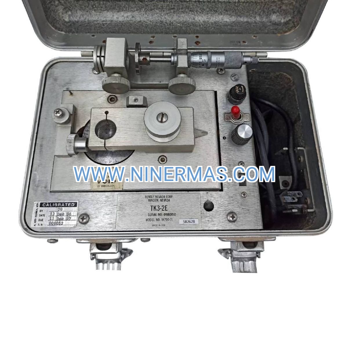
Q: How do I verify proper transducer operation after installation?
A: Use a Bently Nevada TK-3 test kit, Fluke 87V multimeter, or equivalent proximitor tester to measure DC gap voltage and perform dynamic response checks. At 50 mils gap, expect -8 to -10 VDC output. Move a steel feeler gauge toward/away from the probe tip while monitoring voltage change; should observe approximately -200 mV per mil of displacement. Erratic readings indicate cable damage, connector issues, or proximitor malfunction.
Q: What target material and surface finish specifications are required?
A: The probe requires ferromagnetic target material, typically 4140 alloy steel or equivalent magnetic permeability. Minimum shaft diameter is 75mm (3 inches) to avoid curvature effects on linearity. Surface finish should be 32 microinch Ra (0.8 micron) or smoother to minimize electrical runout. Avoid chrome plating, thermal spray coatings, or case-hardened surfaces that alter magnetic properties.
Q: What is the maximum cable length between probe and proximitor module?
A: Standard integral cables are available in 1m, 5m, and 9m lengths (specify during ordering). Maximum recommended cable length is 9 meters (30 feet) to maintain signal integrity and frequency response. For longer distances, consider using extension cables with impedance-matched connectors or relocating the proximitor closer to the measurement point.
Request Technical Consultation & Quotation
To receive detailed system recommendations, application-specific configuration guidance, or project quotations, please provide the following information to our engineering team:
- Project name and site location
- Machinery type and manufacturer (turbine, compressor, motor, etc.)
- Operating speed range (RPM) and maximum anticipated vibration amplitude
- Number of measurement points and monitoring planes required
- Shaft diameter and material at probe installation locations
- Ambient temperature range and hazardous area classification (if applicable)
- Existing monitoring system infrastructure (DCS, PLC, standalone monitors)
- Delivery timeline and installation schedule
Our application engineers will respond within one business day with validated product selections, system architecture recommendations, and commercial proposals tailored to your project requirements.
© 2026 NINERMAS COMPANY LIMITED. All rights reserved.
Original Source: https://ninermas.com
Contact: sale@ninermas.com | +0086 187 5021 5667

Contact Info
-
Address:22 / F, South Wo Hang building, 148 Wing Lok Street, Sheung Wan, Western District, Hong Kong
-
Phone:+8618750215667
-
Email: