
Description
8mm Proximity Probe for Industrial Vibration Monitoring (3300 XL Compatible)
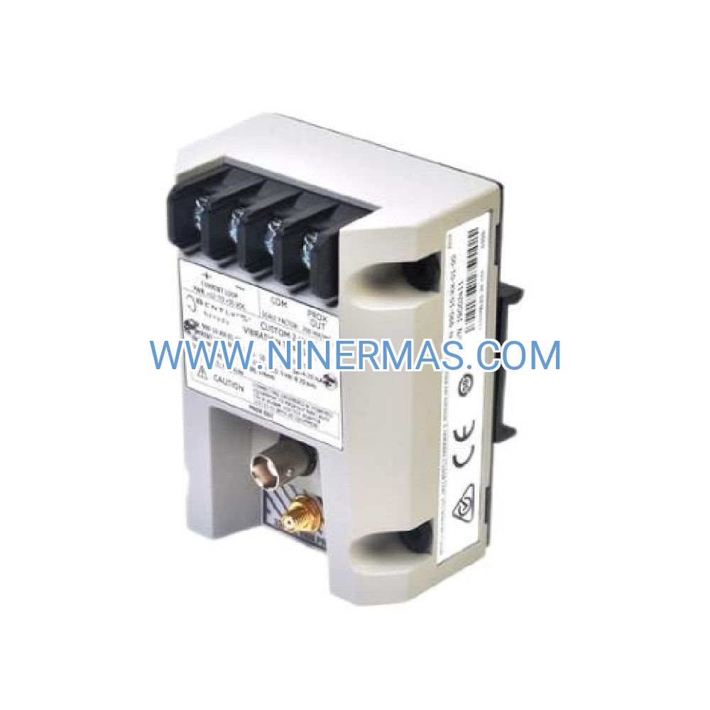
The 330140-08-05-11-00-00 is an industrial-grade 8mm proximity transducer designed for continuous shaft vibration and axial position measurement in critical rotating equipment. Engineered with hermetically sealed stainless steel construction, this non-contact sensor delivers precise displacement data across extreme temperature ranges, making it the preferred choice for turbomachinery protection in power generation, petrochemical processing, and heavy industrial applications.
Suitable for steam turbines, gas compressors, centrifugal pumps, and high-speed motors, this probe addresses common challenges including bearing wear detection, rotor eccentricity tracking, thrust position monitoring, and early fault identification. By providing real-time gap voltage output proportional to target distance, it enables predictive maintenance strategies that reduce unplanned downtime and prevent catastrophic machinery failures.
Through standardized 5/8-18 UNF threading and factory calibration for 4140 alloy steel targets, the 330140-08-05-11-00-00 offers rapid installation, exceptional linearity (±1% FSO), and long-term stability without field recalibration. Ideal for design engineers, maintenance teams, OEM integrators, and plant reliability specialists seeking proven condition monitoring solutions. Contact our application engineers for system configuration assistance and technical specifications tailored to your machinery profile.
Core Features & Technical Advantages
- Wide Frequency Response (0–10 kHz)
Captures both slow-roll baseline measurements and high-frequency vibration events, enabling comprehensive analysis from startup transients to steady-state operation across variable speed machinery. - Extended Temperature Range (-40°C to +105°C)
Maintains calibration accuracy in harsh environments including steam turbine casings, compressor discharge zones, and outdoor installations subject to seasonal extremes, eliminating temperature-induced drift. - Hermetically Sealed Construction
Stainless steel housing with laser-welded seams provides IP67-equivalent protection against moisture ingress, oil mist, and particulate contamination, ensuring reliable operation in demanding industrial atmospheres. - Factory-Calibrated Output (-7.87 V/mm)
Pre-configured for 3300 XL proximitor modules with documented linearity curves, reducing commissioning time and eliminating field calibration errors that compromise measurement integrity. - Flexible Cable Configurations
Standard 5-meter integral cable with options for custom lengths up to 9 meters, supporting distributed monitoring architectures and retrofit installations where probe-to-proximitor distances vary. - Multi-Layer EMI Shielding
Integrated electromagnetic interference protection maintains signal fidelity in electrically noisy environments near VFD panels, motor controllers, and high-voltage switchgear.
Typical Application Scenarios
This proximity probe serves industries where machinery reliability directly impacts production continuity and safety compliance:
- Power Generation & Cogeneration Plants
Monitors steam turbine journal bearings, generator thrust positions, and balance-of-plant rotating equipment. Integrates with DCS/SCADA systems for automated trip logic and historical trending in combined-cycle, coal-fired, and nuclear facilities. - Oil & Gas Processing Facilities
Tracks compressor rotor dynamics in pipeline booster stations, LNG liquefaction trains, and offshore platforms. Detects surge conditions, aerodynamic instability, and bearing degradation before performance loss or mechanical damage occurs. - Chemical & Petrochemical Manufacturing
Provides continuous surveillance of centrifugal pump impeller clearances, agitator shaft runout, and reactor circulation system components. Supports API 670 compliance for machinery protection systems in hazardous area classifications. - Pulp & Paper Mills
Measures vibration on high-speed paper machine rolls, refiner disc assemblies, and recovery boiler induced draft fans. Enables condition-based maintenance scheduling that maximizes uptime during peak production periods. - Steel & Metal Production
Monitors rolling mill backup rolls, blast furnace blower sets, and continuous casting machine pinch rolls. Withstands elevated ambient temperatures and heavy particulate loading characteristic of primary metals environments.
Technical Parameters & Selection Guide
To ensure optimal performance and compatibility, reference the following specifications when designing your monitoring system:
| Parameter | Specification |
|---|---|
| Model Number | 330140-08-05-11-00-00 |
| Probe Diameter | 8mm (0.315 inches) |
| Thread Size | 5/8-18 UNF-2A |
| System Compatibility | 3300 XL Proximitor (330180/330780 series) |
| Operating Temperature | -40°C to +105°C (-40°F to +221°F) |
| Frequency Response | 0 Hz to 10 kHz (-3dB) |
| Linear Range | 0.5mm to 2.0mm (typical with 4140 steel target) |
| Cable Length | 5 meters standard (custom lengths available) |
| Housing Material | 300-series stainless steel, hermetically sealed |
| Weight | Approximately 200 grams |
| Hazardous Area Rating | Class I Div 2 (when used with approved barriers) |
Selection Considerations: When specifying this probe, confirm the following project parameters: target shaft material and surface finish (4140 steel recommended), required measurement range and linearity tolerance, mounting boss thread compatibility, cable routing path and required length, ambient temperature profile at installation location, and proximitor module model for system integration. For non-standard targets (aluminum, titanium, Inconel) or custom cable terminations, consult our engineering team with machinery drawings and application details.
System Integration & Advanced Capabilities
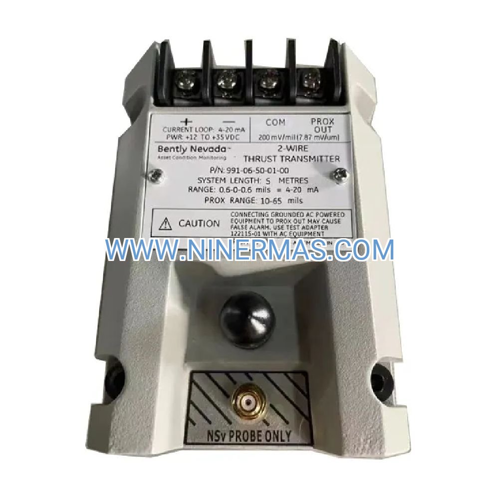
The 330140-08-05-11-00-00 functions as the sensing element within a complete 3300 XL eddy current measurement chain. When connected to a 330180-series proximitor module via extension cable, the system converts mechanical displacement into industry-standard 4-20mA or -10 to +10 VDC outputs compatible with PLC analog inputs, DCS historian tags, and dedicated vibration monitors.
For multi-bearing machines requiring XY vibration analysis, deploy probes in orthogonal pairs (typically at 90° orientation) to capture radial orbit patterns. Combine with keyphasor sensors for phase-referenced analysis that distinguishes unbalance, misalignment, looseness, and rub conditions. Integration with Bently Nevada 3500 rack-based monitoring systems enables automated alarm setpoints, shutdown logic, and predictive analytics using machine learning algorithms.
Advanced installations may incorporate:
- Dual-probe differential measurement for true axial position (thrust bearing monitoring)
- Temperature-compensated proximitor modules for ultra-precision applications
- Fiber-optic extension systems for extreme EMI environments or long-distance transmission
- Wireless gateway integration for remote asset monitoring and cloud-based diagnostics
Delivery, Quality Assurance & Technical Support
Lead Time: Standard catalog items ship within 3–5 business days from regional distribution centers. Custom cable lengths or special certifications require 10–15 business days. Expedited processing available for critical outage support.
Warranty Coverage: Each probe includes a comprehensive 12-month warranty against defects in materials and workmanship from date of shipment. Extended warranty programs available for fleet purchases and long-term service agreements.
Documentation Package: Every unit ships with calibration certificate traceable to NIST standards, dimensional outline drawing, electrical connection diagram, installation torque specifications, and recommended proximitor pairing guide. Digital copies provided in PDF format for asset management systems.
Technical Assistance: Our application engineering team provides pre-sale consultation for system design, post-installation commissioning support via phone/email, and on-site services for complex multi-channel installations (subject to geographic availability and service agreement terms). Training resources include installation videos, troubleshooting flowcharts, and integration guides for common DCS platforms.
Frequently Asked Questions (FAQ)
Q: How does the 330140-08-05-11-00-00 proximity probe interface with existing monitoring systems?
A: The probe connects to a 3300 XL proximitor module (such as 330180-91-05) which converts the probe's raw signal into calibrated voltage or current output. This output feeds directly into PLC analog input cards, DCS channels, or dedicated vibration monitors. Ensure your proximitor module matches your control system's input requirements (typically 4-20mA or ±10VDC).
Q: What is the maximum number of probes I can install on a single machine?
A: There is no theoretical limit—installations range from 2 probes (single radial plane) to 20+ probes on large turbine-generator sets. Practical constraints include available mounting locations, proximitor channel count, and monitoring system capacity. For machines above 10,000 RPM or API 670 compliance, minimum 2 probes per bearing (XY configuration) is standard practice.
Q: What energy savings or efficiency improvements can I expect from vibration monitoring?
A: While the probe itself doesn't reduce energy consumption, early detection of misalignment, imbalance, or bearing wear prevents efficiency degradation. Studies show unaddressed vibration issues can increase energy consumption by 5–15% due to friction losses and reduced mechanical efficiency. Predictive maintenance enabled by continuous monitoring typically reduces maintenance costs by 25–30% and extends mean time between failures by 40–60%.
Q: What are the environmental and installation requirements for this proximity probe?
A: The probe requires a threaded mounting boss (5/8-18 UNF) machined perpendicular to the shaft surface, with adequate clearance for the 8mm probe body. Ambient temperature must remain within -40°C to +105°C. For hazardous area installations (Class I Div 2), use intrinsically safe barriers between proximitor and probe. Protect cable routing from sharp edges, excessive heat sources (>105°C), and mechanical damage. Minimum bend radius: 25mm.
Q: Can this probe support remote monitoring and wireless data transmission?
A: Yes, when paired with compatible proximitor modules and wireless gateway devices (such as Bently Nevada 1900/65A), the system can transmit vibration data to cloud platforms or remote monitoring centers. The probe output feeds the proximitor, which connects to a wireless transmitter via 4-20mA loop. This enables IIoT integration, mobile app access, and centralized fleet monitoring across multiple facilities. Consult our team for wireless architecture design and cybersecurity considerations.
Q: How do I verify the proximity probe is functioning correctly after installation?
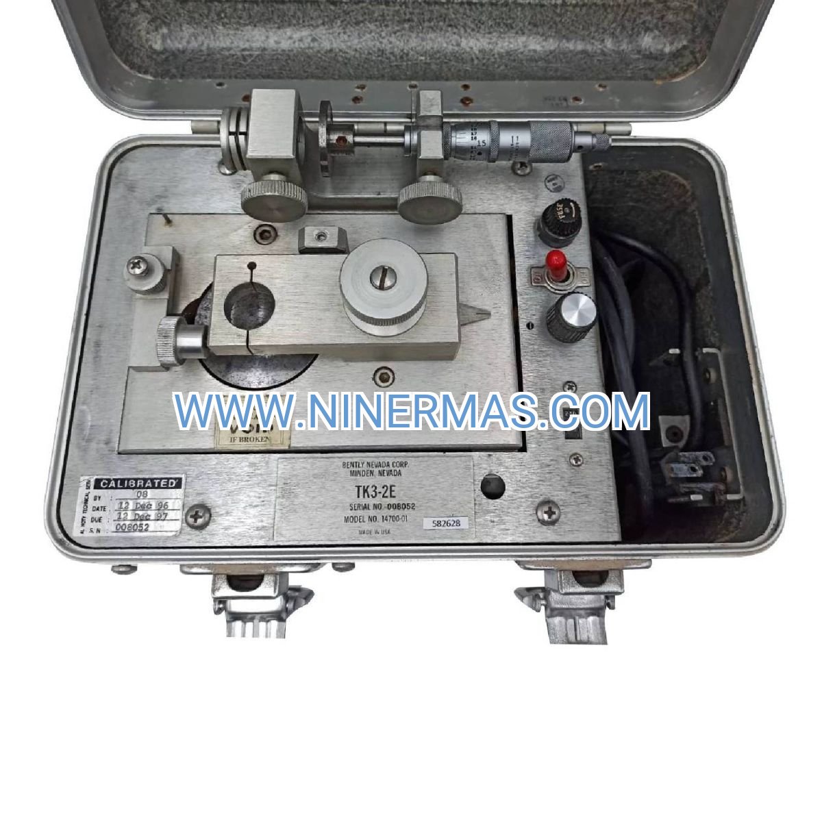
A: Use a calibrated feeler gauge or micrometer to establish known gap distances between probe tip and target surface. Measure the proximitor output voltage at each gap increment (typically 0.5mm, 1.0mm, 1.5mm, 2.0mm). Plot voltage vs. distance—the curve should match the factory calibration data within ±5%. Alternatively, use a Bently Nevada TK-3 test kit for automated verification. Check for cable continuity, proper grounding, and absence of electrical noise on the signal line.
Request Technical Consultation & Custom Quotation
To receive a tailored system recommendation, detailed pricing, or application-specific engineering support, please provide the following information to our technical sales team:
- Project name and industry sector
- Equipment type and operating speed range (RPM)
- Number of monitoring points and bearing locations
- Shaft material, diameter, and surface finish
- Required cable lengths and routing constraints
- Existing monitoring infrastructure (proximitor models, DCS/PLC platform)
- Environmental conditions (temperature, humidity, hazardous area classification)
- Delivery timeline and installation schedule
Our application engineers will respond within 24 hours with system architecture recommendations, bill of materials, and project-specific pricing. For urgent outage support or emergency replacements, contact our 24/7 technical hotline.
© 2026 NINERMAS COMPANY LIMITED. All rights reserved.
Original Source: https://ninermas.com
Contact: sale@ninermas.com | +0086 187 5021 5667

Contact Info
-
Address:22 / F, South Wo Hang building, 148 Wing Lok Street, Sheung Wan, Western District, Hong Kong
-
Phone:+8618750215667
-
Email: