Description
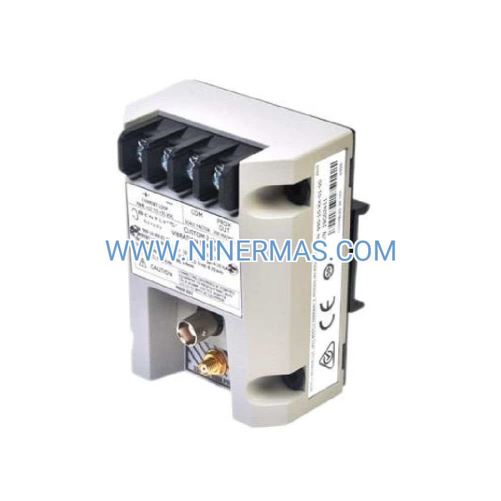
Bently Nevada 3300/20 Dual Thrust Position Monitor (Industrial Axial Bearing Protection System)
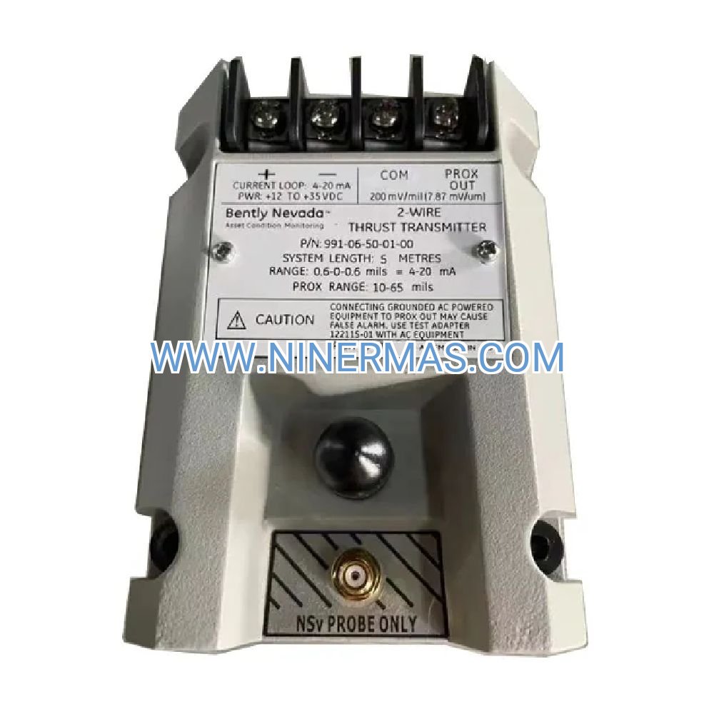
The Bently Nevada 3300/20-12-01-02-03-02 is an industrial-grade thrust position monitor designed for continuous axial shaft displacement measurement in critical rotating machinery. Through dual-channel proximity sensor integration and real-time analog signal processing, it delivers precision thrust bearing surveillance, enabling early fault detection and preventing catastrophic bearing failures in turbines, compressors, and high-speed rotating equipment.
Ideal for applications in power generation plants, petrochemical facilities, oil & gas compression stations, and heavy industrial manufacturing environments, this monitor addresses common challenges including undetected thrust bearing wear, axial rotor displacement beyond safe limits, inadequate alarm response time, and lack of measurement redundancy during maintenance cycles.
Built on proven Bently Nevada engineering standards with customizable alarm setpoints and universal DCS compatibility, the 3300/20 series offers significant advantages: dual-channel redundancy for uninterrupted protection, field-configurable measurement ranges, buffered 4-20mA outputs for long-distance signal transmission, and seamless integration with existing machinery protection systems. Suitable for design engineers, EPC contractors, plant maintenance teams, and OEM equipment integrators. Contact our application engineers for customized configuration recommendations and technical quotations.
Core Features & Advantages
- Dual-Channel Redundant Architecture
Two independent measurement channels provide continuous thrust position monitoring even during sensor maintenance or single-point failures, ensuring uninterrupted machinery protection and compliance with safety integrity level (SIL) requirements. - Precision Axial Displacement Measurement
Configurable measurement ranges from 0-500 mils (0-12.7mm) with ±1% full-scale accuracy, compatible with Bently Nevada 3300 XL 8mm and 11mm proximity probes for reliable thrust collar position tracking. - Flexible Alarm & Output Configuration
Dual setpoint alarms (Alert/Danger) per channel with independent relay contacts, plus buffered 4-20mA proportional outputs enable integration with DCS, PLC, SCADA, and standalone alarm panels for multi-tier protection strategies. - Robust Industrial Design
Operates reliably in harsh environments from -30°C to +65°C (-22°F to +149°F), IP20 panel-mount enclosure, 24VDC power supply with wide input tolerance (18-30VDC), and CE/CSA/FM certifications for hazardous location installations. - Simplified Installation & Maintenance
Front-panel DIP switches and potentiometers allow field configuration without specialized software, LED status indicators provide instant diagnostic feedback, and standardized terminal blocks reduce installation time and wiring errors. - Universal System Compatibility
Seamless integration with Honeywell, Emerson DeltaV, Yokogawa, Siemens PCS7, ABB, and Schneider Electric control platforms through industry-standard 4-20mA analog signals and dry contact relay outputs.
Typical Application Scenarios
This thrust position monitor is engineered for installations where axial shaft displacement control and thrust bearing integrity are critical to operational safety and equipment longevity, particularly in:
- Steam & Gas Turbine Protection
Monitors axial rotor position in power generation turbines to prevent thrust bearing damage from thermal expansion, load transients, or lubrication system failures, protecting multi-million dollar assets from catastrophic failure. - Centrifugal Compressor Surveillance
Tracks compressor rotor axial displacement in natural gas pipeline stations, refinery process units, and air separation plants, detecting thrust bearing wear before performance degradation or unplanned shutdowns occur. - Large Motor & Generator Monitoring
Provides continuous thrust position measurement in high-power induction motors, synchronous generators, and variable-speed drive applications where magnetic pull forces create axial loading on thrust bearings. - Pump Thrust Bearing Condition Assessment
Monitors axial shaft movement in multistage centrifugal pumps, boiler feed pumps, and pipeline transfer pumps, enabling predictive maintenance scheduling based on actual bearing wear trends rather than time-based intervals. - Hydroelectric & Wind Turbine Applications
Measures generator thrust bearing position in hydroelectric installations and large wind turbine drivetrains, where axial hydraulic forces and rotor weight create continuous thrust loading requiring precision monitoring.
Technical Parameters & Selection Guide
To facilitate engineering design and equipment selection, we provide standardized configuration options with customization available for project-specific requirements:
| Parameter | Specification |
|---|---|
| Model Number | 3300/20-12-01-02-03-02 |
| Input Channels | Dual independent channels (Channel A & B) |
| Measurement Range | 0-500 mils (0-12.7mm) configurable |
| Accuracy | ±1% of full scale |
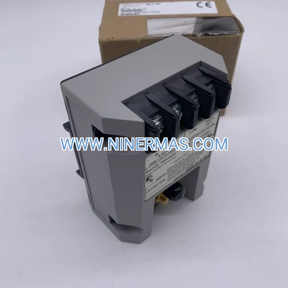
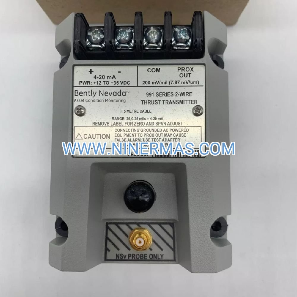
| Output Signal | 4-20mA proportional (buffered, isolated) |
| Alarm Relays | 4 SPDT relays (2 per channel: Alert/Danger) |
| Relay Rating | 5A @ 250VAC / 30VDC resistive load |
| Power Supply | 24VDC nominal (18-30VDC operating range) |
| Power Consumption | < 8W typical |
| Operating Temperature | -30°C to +65°C (-22°F to +149°F) |
| Storage Temperature | -40°C to +85°C (-40°F to +185°F) |
| Humidity | 5% to 95% RH non-condensing |
| Enclosure Rating | IP20 (panel mount) |
| Mounting | DIN rail or panel mount (hardware included) |
| Dimensions (H×W×D) | 133mm × 48mm × 175mm (5.24" × 1.89" × 6.89") |
| Weight | 0.2 kg (0.44 lbs) |
| Certifications | CE, CSA, FM approved (Class I Div 2) |
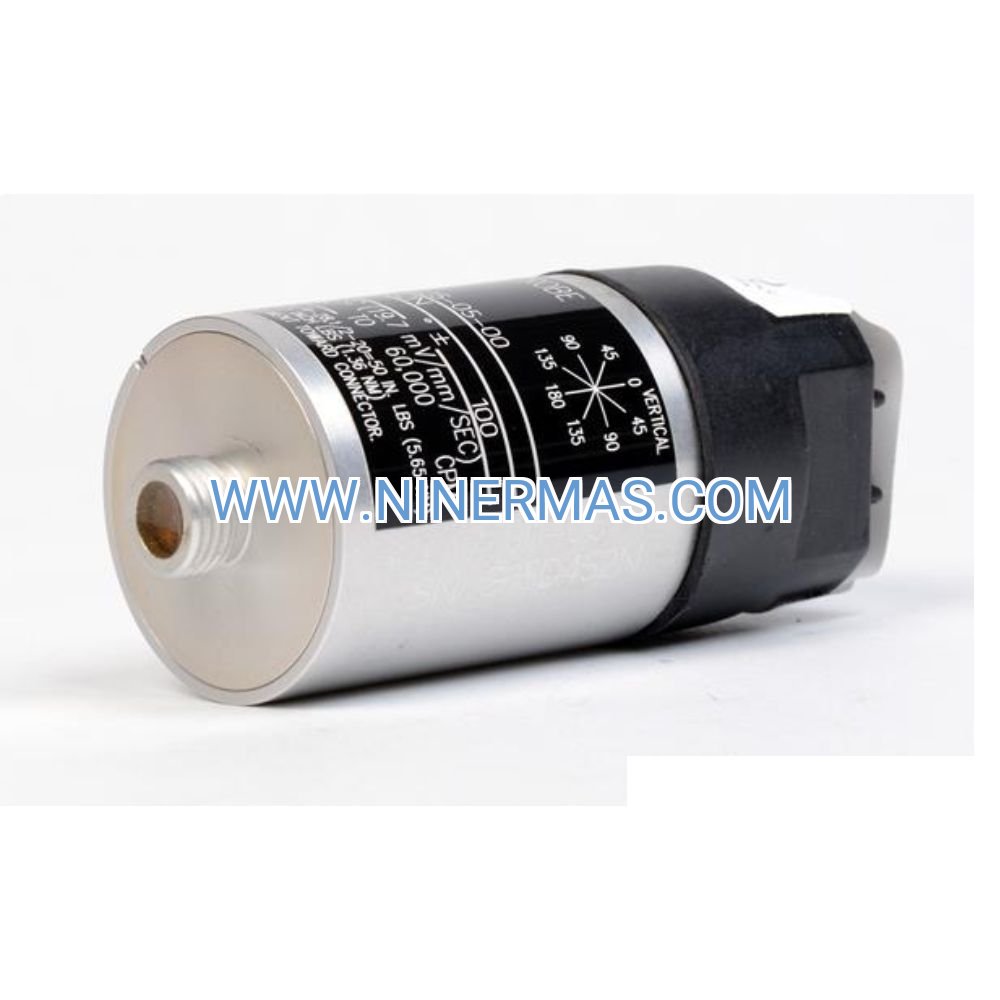
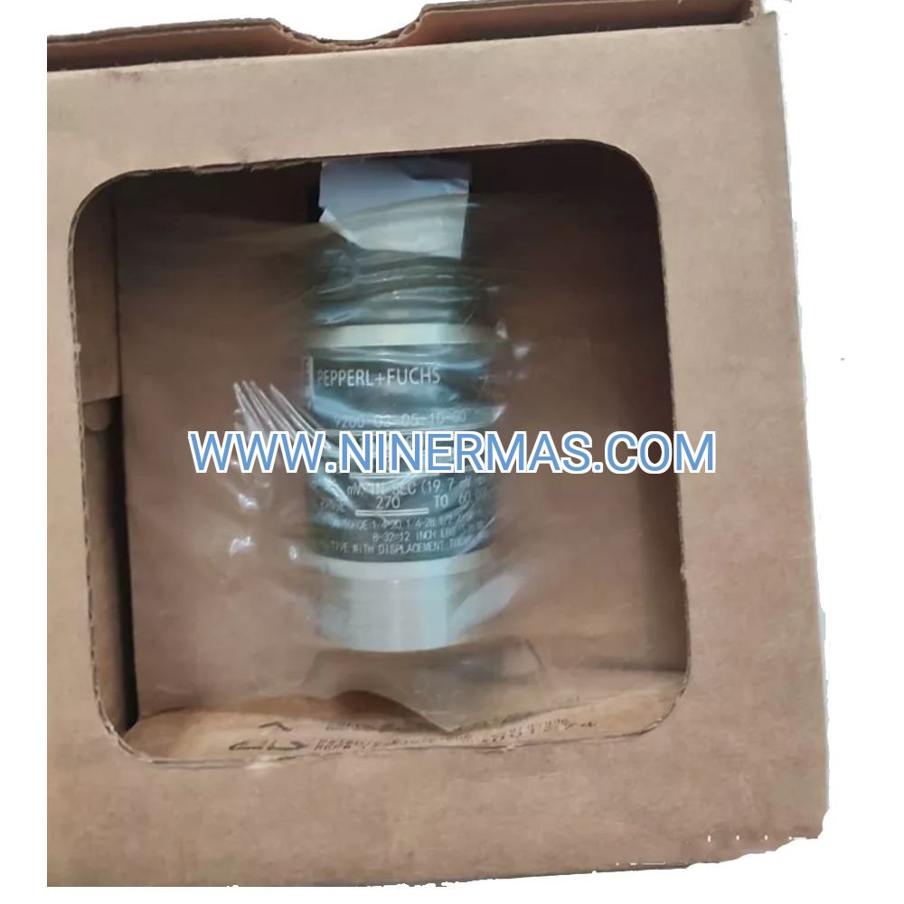
| Compatible Sensors | Bently Nevada 3300 XL 8mm/11mm proximity probes |
Selection Recommendations: When specifying this monitor, consider the following application parameters: maximum expected axial shaft displacement under normal and fault conditions, required alarm setpoint values (typically 50-75% of bearing clearance for Alert, 80-90% for Danger), control system input requirements (4-20mA loop impedance, relay contact ratings), available panel space and mounting orientation, ambient temperature range at installation location, and proximity probe cable length (affects sensor system sensitivity). For application-specific configuration assistance, please provide machinery type, operating speed range, thrust bearing design clearances, and existing monitoring system architecture. Our application engineers will recommend optimal sensor placement, alarm setpoint strategies, and system integration approaches.
Extended Functionality & Integration
- Multi-Point Monitoring Networks
Multiple 3300/20 monitors can be deployed across a facility to create comprehensive machinery protection networks, with centralized alarm annunciation through DCS or dedicated alarm management systems. - Trending & Diagnostic Capabilities
The 4-20mA analog outputs enable continuous data logging in historian systems (OSIsoft PI, Honeywell PHD, GE Proficy) for long-term thrust position trending, bearing wear analysis, and predictive maintenance program development. - Retrofit & Upgrade Pathways
Direct replacement for legacy Bently Nevada 7200 series monitors with minimal wiring modifications, and migration path to 3500 rack-based systems when remote configuration and advanced diagnostics are required. - Hazardous Area Installations
FM and CSA certifications permit installation in Class I Division 2 hazardous locations when properly installed per NEC/CEC requirements, suitable for oil & gas and chemical processing environments.
Delivery, Service & Quality Assurance
Lead Time: Standard configuration units typically ship within 3-5 business days from stock. Custom-configured monitors or bulk orders require 10-15 business days for factory programming and testing.
Warranty Coverage: All units include a comprehensive 12-month manufacturer warranty covering defects in materials and workmanship under normal operating conditions. Extended warranty programs available upon request.
Technical Support: Our application engineering team provides pre-sale consultation for system design, installation guidance including sensor placement and wiring diagrams, commissioning support via phone/email, and post-installation troubleshooting assistance. On-site commissioning services available for critical installations (regional availability varies).
Documentation Package: Each monitor ships with complete technical documentation including installation manual with dimensional drawings and mounting templates, electrical connection diagrams and terminal identification, configuration procedure for alarm setpoints and output scaling, sensor compatibility matrix and cable length guidelines, and troubleshooting flowcharts with LED diagnostic codes.
Quality Certifications: Manufactured under ISO 9001:2015 quality management systems with full traceability. CE marking for European Union compliance, CSA certification for Canadian installations, and FM approval for North American hazardous locations.
Frequently Asked Questions (FAQ)
Q: What proximity sensors are compatible with the 3300/20 thrust position monitor?
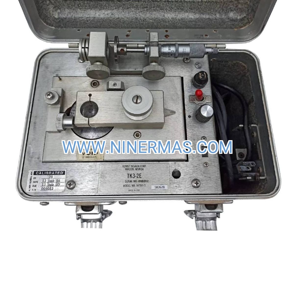
A: This monitor is designed for use with Bently Nevada 3300 XL series proximity probes, specifically 8mm and 11mm diameter sensors. Recommended models include 330525 Velomitor series and 330100 Proximitor series. Sensor system sensitivity must be calibrated to the target thrust collar material (typically 4140 steel) and probe-to-target gap. Standard sensor cable lengths up to 5 meters (16 feet) are supported; longer runs may require signal conditioning.
Q: Can the 3300/20 monitor interface with existing DCS or PLC control systems?
A: Yes, the monitor provides universal compatibility through industry-standard interfaces. The buffered 4-20mA analog outputs (one per channel) connect directly to analog input modules on all major DCS platforms including Honeywell, Emerson DeltaV, Yokogawa, Siemens, ABB, and Schneider Electric systems. The four SPDT relay contacts (Alert/Danger for each channel) interface with discrete input modules or standalone alarm panels. Loop impedance up to 600Ω is supported for 4-20mA circuits.
Q: What is the recommended installation configuration for dual-channel thrust monitoring?
A: Standard practice uses two proximity probes positioned 180° apart on the thrust collar (or thrust bearing housing), with each probe connected to one monitor channel. This configuration provides measurement redundancy and averages out any thrust collar runout or eccentricity. Probes should be mounted in the axial direction, perpendicular to the thrust collar face, with initial gap settings per Bently Nevada sensor installation guidelines (typically 40-60 mils or 1.0-1.5mm).
Q: How are alarm setpoints configured on the 3300/20 monitor?
A: Alarm setpoints are configured via front-panel potentiometers (one Alert and one Danger setpoint per channel). Setpoints are adjustable across the full measurement range and are typically set based on thrust bearing design clearances: Alert at 50-75% of maximum allowable displacement, Danger at 80-90%. DIP switches select alarm logic (normally energized or de-energized) and output scaling. No external software or programming tools are required for field configuration.
Q: Does the 3300/20 support remote configuration or digital communication protocols?
A: The 3300/20 series uses analog outputs and relay contacts without digital communication capabilities. Configuration is performed locally via front-panel controls. For applications requiring remote configuration, digital communication (Modbus, HART, etc.), or advanced diagnostic features, consider upgrading to the Bently Nevada 3500 rack-based monitoring system with network connectivity and condition monitoring software integration.
Q: What maintenance is required for the thrust position monitoring system?
A: The monitor itself is solid-state electronics requiring no routine maintenance beyond periodic verification of alarm setpoint accuracy (annually recommended). Proximity sensors should be inspected during scheduled machinery outages for cable damage, connector integrity, and probe tip condition. Thrust collar target surface should be checked for corrosion, pitting, or coating buildup that could affect measurement accuracy. Calibration verification using a precision micrometer or dial indicator is recommended every 2-3 years or per plant maintenance procedures.
Request Technical Consultation & Quotation
To receive detailed application engineering support, customized configuration recommendations, or project quotations, please provide the following information to our technical sales team:
- Project name and application description (machinery type, operating environment)
- Rotating equipment specifications (turbine/compressor model, operating speed range, shaft diameter)
- Thrust bearing design parameters (bearing type, axial clearance, maximum expected displacement)
- Existing monitoring system architecture (DCS/PLC platform, available I/O, communication protocols)
- Installation environment conditions (ambient temperature range, hazardous area classification if applicable)
- Quantity required and desired delivery schedule
- Any special requirements (extended warranty, on-site commissioning, training, spare parts kits)
Our application engineers will respond within 24 business hours with technical recommendations, system integration guidance, and commercial quotations tailored to your specific requirements.
© 2026 NINERMAS COMPANY LIMITED. All rights reserved.
Original Source: https://ninermas.com
Contact: sale@ninermas.com | +0086 187 5021 5667

Contact Info
-
Address:22 / F, South Wo Hang building, 148 Wing Lok Street, Sheung Wan, Western District, Hong Kong
-
Phone:+8618750215667
-
Email: