Description
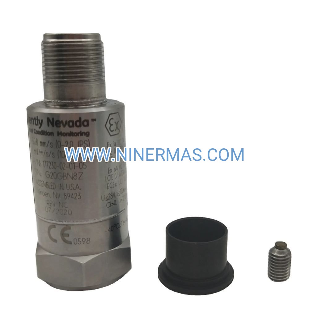
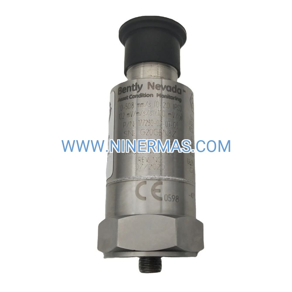
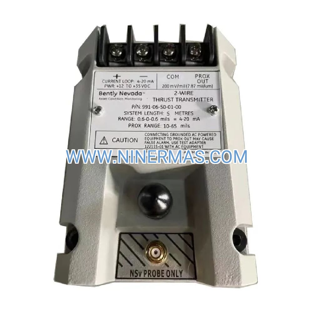
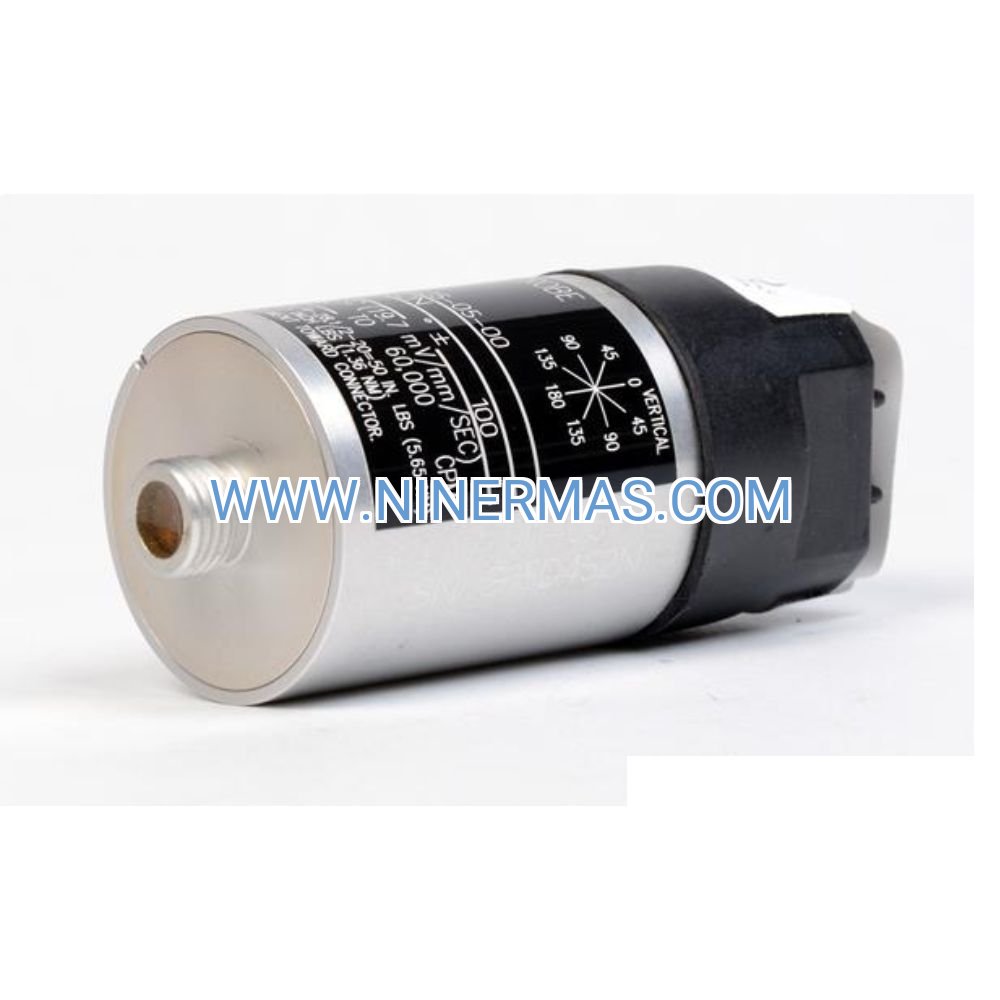
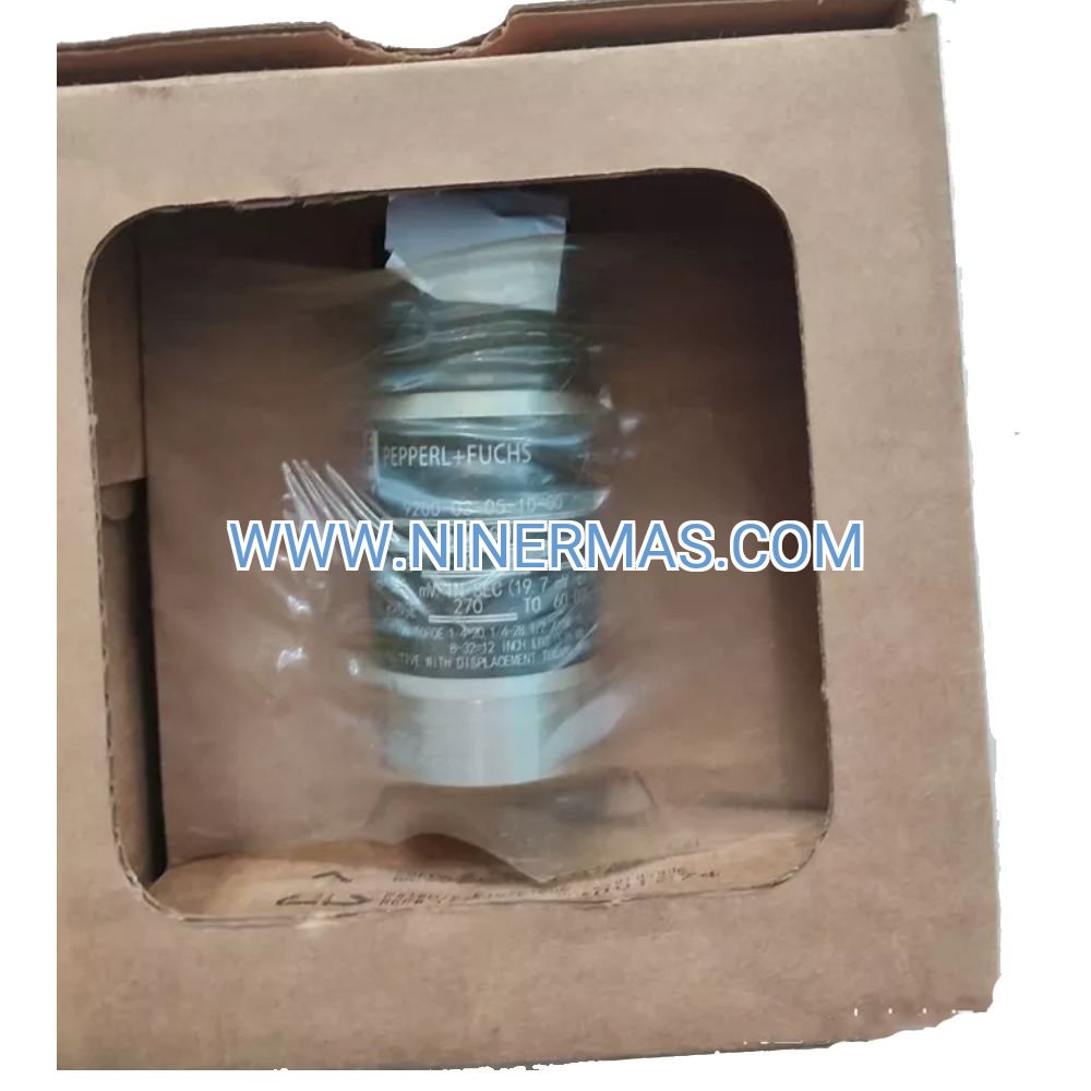
177230-02-01-CN Industrial Velocity Transmitter (ATEX/IECEx Certified)
Engineered for continuous vibration surveillance in explosive atmospheres, the Bently Nevada 177230-02-01-CN combines piezoelectric sensing technology with multi-certification compliance to deliver actionable velocity data from rotating and reciprocating assets. This transmitter transforms mechanical motion into standardized 4-20mA signals, enabling early fault detection across pumps, motors, gearboxes, and process equipment operating in Zone 1/Division 1 classified locations.
Built around a 316L stainless steel enclosure with hermetically sealed electronics, the unit withstands corrosive chemicals, temperature extremes (-40°C to +85°C), and mechanical shock up to 1,000g peak. The 0-50.8 mm/s measurement span captures vibration amplitudes from normal operation through incipient failure stages, while the 10 Hz to 1 kHz frequency bandwidth resolves bearing defects, unbalance, misalignment, and gear mesh anomalies before they escalate into unplanned downtime.
Integration with Bently Nevada 3300/3500 racks, Emerson DeltaV controllers, and third-party SCADA platforms requires no custom programming—the industry-standard current loop output connects directly to analog input modules. Whether you're implementing ISO 20816 compliance monitoring or building a comprehensive asset performance management system, this transmitter provides the foundational velocity data that condition-based maintenance strategies depend on.
Technical Specifications & Performance Characteristics
| Parameter | Specification |
|---|---|
| Velocity Range | 0 to 50.8 mm/s (0 to 2.0 in/s) RMS |
| Frequency Response | 10 Hz to 1 kHz (±3 dB) |
| Output Signal | 4-20 mA current loop (2-wire) |
| Power Supply | 18-30 VDC (loop-powered) |
| Hazardous Area Approvals | ATEX, IECEx, CSA/NRTL/C (Class I Div 1) |
| Housing Material | 316L stainless steel (NACE MR0175 compliant) |
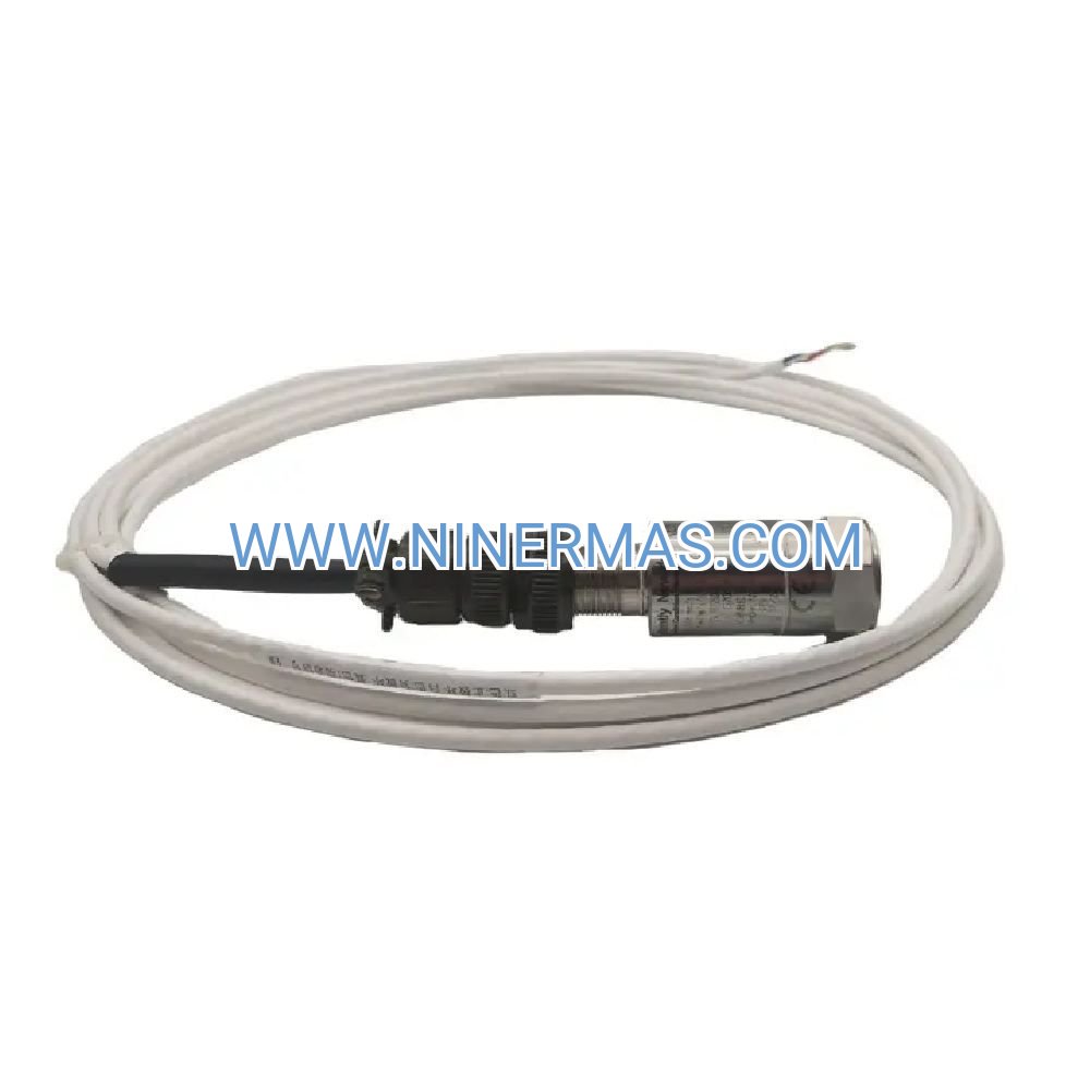
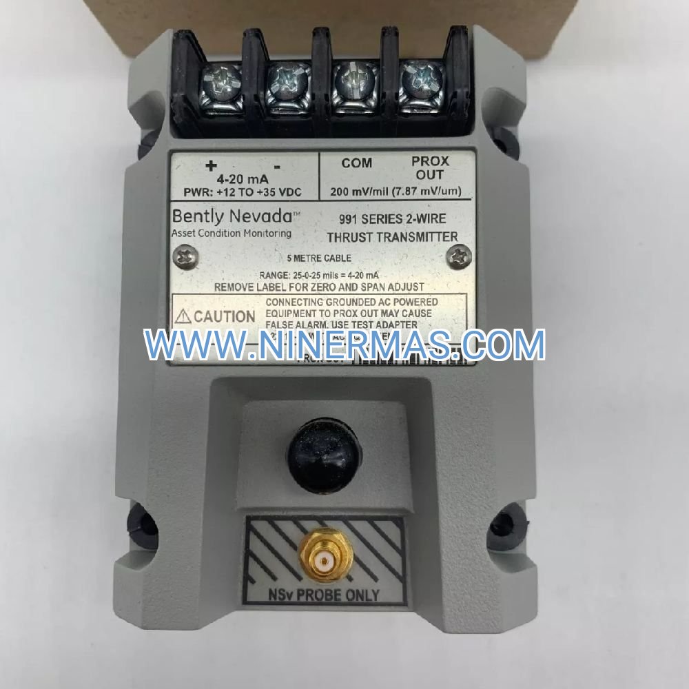
| Connector | MIL-C-5015 3-pin, stainless steel |
| Operating Temperature | -40°C to +85°C (-40°F to +185°F) |
| Shock Survival | 1,000g peak (11 ms duration) |
| Electrical Isolation | >10⁸ Ω @ 50 VDC |
| Mounting Thread | M6×1, M8×1.25, ¼-28 UNF (adapter included) |
| Weight | 131 g (4.62 oz) |
Key Advantages for Industrial Reliability Programs
→ Hazardous Location Compliance: Triple-certified (ATEX/IECEx/CSA) for Zone 1/Div 1 installations eliminates permitting delays and ensures regulatory compliance in petrochemical, pharmaceutical, and grain handling facilities
→ Balanced Frequency Sensitivity: 10 Hz to 1 kHz bandwidth captures both low-speed imbalance (1×RPM) and high-frequency bearing tones (BPFO/BPFI) in a single measurement—no need for multiple sensor types
→ Universal System Integration: 4-20mA output interfaces with 95% of installed DCS/PLC infrastructure without signal conditioning modules, reducing installation costs by $200-400 per point
→ Corrosion-Resistant Construction: 316L stainless steel withstands H₂S, chlorides, and caustic washdowns common in offshore platforms, pulp mills, and food processing plants—typical service life exceeds 15 years
→ Simplified Calibration Verification: Factory-calibrated with NIST-traceable certification; field verification requires only a 4-20mA simulator and vibration shaker (no specialized electronics needed)
→ Low Installation Complexity: 2-wire loop-powered design eliminates separate power supplies and reduces conduit fill by 33% compared to 3-wire accelerometers
Industrial Application Scenarios
Centrifugal Pump Monitoring (Refineries & Chemical Plants)
Challenge: Cavitation and bearing wear in API 610 pumps cause unplanned shutdowns costing $50,000-150,000 per incident
Solution: Mount 177230-02-01-CN on pump bearing housings to track velocity trends; 20% increase over baseline triggers inspection, preventing catastrophic seal failures
Result: Shift from reactive to predictive maintenance reduces pump-related downtime by 60-75%
Electric Motor Condition Monitoring (Manufacturing Facilities)
Challenge: Rotor bar cracks and bearing degradation in 200-500 HP motors go undetected until complete failure
Solution: Install transmitters on motor drive-end and non-drive-end bearings; velocity spectra reveal 2×line frequency (rotor bars) and bearing fault frequencies 8-12 weeks before failure
Result: Planned bearing replacements during scheduled outages eliminate emergency repairs and extend motor life 30%
Gearbox Health Assessment (Wind Turbines & Mining)
Challenge: Gear tooth pitting and shaft misalignment in planetary gearboxes require $80,000-200,000 replacements
Result: Continuous velocity monitoring detects gear mesh frequency sidebands 4-6 months before tooth breakage, enabling oil analysis confirmation and planned interventions
Fan & Blower Surveillance (HVAC & Ventilation Systems)
Challenge: Belt tension loss and bearing lubrication failures cause comfort complaints and energy waste
Solution: Wireless-connected 177230-02-01-CN transmitters monitor fan vibration remotely; automated alerts trigger maintenance before failures impact building occupants
Result: 40% reduction in HVAC service calls and 15% energy savings from optimized fan operation
Compressor Protection (Oil & Gas Production)
Challenge: Reciprocating compressor crosshead wear and valve failures halt production in remote locations
Solution: Velocity transmitters on compressor frame detect abnormal pulsations and bearing impacts; satellite-linked monitoring enables proactive part staging
Result: Mean time between failures increases from 18 to 36 months; parts inventory costs drop 25%
Configuration Selection Guide
Understanding the Model Code: 177230-02-01-CN
✓ Base Model (177230): Seismic velocity transmitter platform with piezoelectric sensing element
✓ Range Option (02): 0-50.8 mm/s—select for high-vibration applications (>25 mm/s normal operation) such as reciprocating compressors, crushers, or poorly balanced fans
✓ Frequency Option (01): 10 Hz to 1 kHz RMS—ideal for machinery operating 600-60,000 RPM where velocity provides optimal fault sensitivity
✓ Certification Option (CN): Combined ATEX/IECEx/CSA approvals for global hazardous area installations
Alternative Configurations Available:
• 177230-00-01-CN: 0-12.7 mm/s range for precision applications (large turbines, critical pumps operating <10 mm/s)
• 177230-01-01-CN: 0-25.4 mm/s range for standard industrial machinery (most motors, pumps, fans)
• 177230-02-02-CN: 3 Hz to 1 kHz peak response for slow-speed equipment (<300 RPM) like kilns, dryers, conveyors
Selection Criteria: Choose measurement range so normal operating velocity falls between 25-75% of full scale. For a motor typically running at 8 mm/s, the 0-25.4 mm/s range (option 01) provides optimal resolution. For a crusher operating at 35 mm/s, the 0-50.8 mm/s range (option 02) prevents saturation during transient events.
Advanced Integration Capabilities
The 177230-02-01-CN transmitter functions as a plug-and-play sensor node within multi-vendor monitoring architectures:
Bently Nevada Ecosystem: Direct connection to 3300 XL 8mm proximitor systems, 3500/42M vibration monitors, and Orbit 60 wireless gateways—configuration files available for download from Bently Nevada Asset Condition Monitoring portal
DCS/PLC Integration: Analog input modules from Emerson DeltaV, Honeywell Experion, Siemens PCS 7, and Rockwell ControlLogix accept 4-20mA signals without scaling—velocity values map linearly (4mA = 0 mm/s, 20mA = 50.8 mm/s)
Wireless Retrofits: Pair with Phoenix Contact RAD-2400-IFS gateways or Emerson Plantweb 1420 adapters to add wireless capability to existing wired transmitters—ideal for remote assets or temporary monitoring campaigns
Cloud Analytics: Stream data to AWS IoT Core, Microsoft Azure IoT Hub, or GE Predix platforms via edge gateways; machine learning algorithms detect anomalies 6-8 weeks earlier than threshold-based alarms
Installation Best Practices & Common Pitfalls
Mounting Surface Preparation: Clean mounting location to bare metal with wire brush; apply thin layer of petroleum jelly or anti-seize compound to threads (not mounting face). Torque to 4-7 N·m using calibrated wrench—over-torquing distorts housing and shifts frequency response.
Magnetic Base Caution: When using magnetic mounting adapters, never snap the base onto the machine—the impact generates 500-1,000g shock spikes that can damage the internal piezoelectric element. Instead, slide the base into position or use the "roll-on" technique to minimize mechanical shock.
Cable Routing: Use shielded twisted-pair cable (Belden 8761 or equivalent); ground shield at DCS/PLC end only to prevent ground loops. Maintain 300mm separation from VFD power cables and 150mm from AC motor leads to minimize EMI coupling.
Electrical Noise Mitigation: In electrically noisy environments (near welders, VFDs, or SCR controllers), install 0.1 µF ceramic capacitor across transmitter terminals and verify >10⁸ Ω isolation resistance before energizing loop.
Temperature Compensation: For applications with >40°C temperature swings, allow 30-minute thermal stabilization after installation before recording baseline readings—piezoelectric sensitivity shifts ±2% per 10°C.
Delivery, Warranty & Technical Support
Standard Lead Time: 3-5 business days for stock configurations (177230-XX-01-CN models); 2-3 weeks for special-order frequency responses or custom cable lengths
Warranty Coverage: 24-month manufacturer's warranty covering defects in materials and workmanship; extended 60-month coverage available for critical service applications
Technical Documentation: Each transmitter ships with NIST-traceable calibration certificate, hazardous area certification documents (ATEX/IECEx/CSA), installation manual, and dimensional drawings in STEP/DWG formats
Application Engineering: Our vibration specialists provide complimentary pre-sale consultation including sensor quantity estimation, mounting location recommendations, and alarm setpoint calculations based on ISO 20816 or API 670 standards
Post-Sale Support: Lifetime technical support via email (response within 4 business hours) and phone (8:00-17:00 CST, Monday-Friday); emergency support available for critical asset failures
Frequently Asked Questions
Q: Can the 177230-02-01-CN transmitter monitor both horizontal and vertical machinery orientations?
A: Yes—the piezoelectric sensing element responds to vibration in the axis perpendicular to the mounting surface regardless of gravity orientation. For comprehensive monitoring, install transmitters in horizontal, vertical, and axial orientations (3 sensors per bearing).
Q: What is the minimum loop resistance required for reliable 4-20mA operation?
A: Maximum loop resistance = (Supply Voltage - 18V) / 0.02A. For a 24 VDC supply: (24-18)/0.02 = 300Ω maximum. Typical installations with 100m of 18 AWG cable (6.4Ω/100m) and a 250Ω DCS input resistor operate with 50% margin.
Q: How does velocity monitoring compare to acceleration measurement for bearing fault detection?
A: Velocity transmitters provide superior sensitivity to bearing defects in the 1-10 kHz range (outer race, inner race, ball spin frequencies) compared to displacement sensors, while avoiding the high-frequency noise amplification inherent in accelerometers. For general machinery <3,600 RPM, velocity offers the best balance of fault sensitivity and signal-to-noise ratio.
Q: Can I use this transmitter in SIL-rated safety instrumented systems?
A: The 177230-02-01-CN is suitable for condition monitoring and alarm functions but is not SIL-certified for safety instrumented shutdown systems. For SIL 2/3 applications, specify Bently Nevada 3300 XL NSv proximitor systems with TÜV certification.
Q: What is the recommended calibration interval for maintaining measurement accuracy?
A: Factory calibration remains valid for 5 years under normal operating conditions. For critical assets or regulatory compliance (FDA, nuclear), annual verification using a vibration calibrator (ISO 16063-21) is recommended. Recalibration is required after any mechanical shock event >1,000g or exposure to temperatures >100°C.
Q: How do I troubleshoot a transmitter reading 4mA continuously?
A: Constant 4mA output indicates either zero vibration (unlikely) or sensor failure. Verify: (1) Mounting torque is 4-7 N·m, (2) Machine is operating, (3) Cable shield is not grounded at both ends, (4) Supply voltage is 18-30 VDC. If all checks pass, the piezoelectric element may be damaged—return unit for factory evaluation.
Start Protecting Your Critical Assets Today
Transform reactive maintenance into predictive reliability with the 177230-02-01-CN velocity transmitter. Our application engineers are ready to help you select the optimal configuration, calculate required sensor quantities, and design a monitoring strategy that reduces unplanned downtime by 60% or more.
Request a technical consultation: Contact our team at sale@ninermas.com or call +0086 187 5021 5667 to discuss your specific monitoring requirements. Volume pricing available for projects requiring 10+ transmitters.
© 2026 NINERMAS COMPANY LIMITED. All rights reserved.
Original Source: https://ninermas.com
Contact: sale@ninermas.com | +0086 187 5021 5667
PDF Specification
Download PDF file here:
Click to Download PDF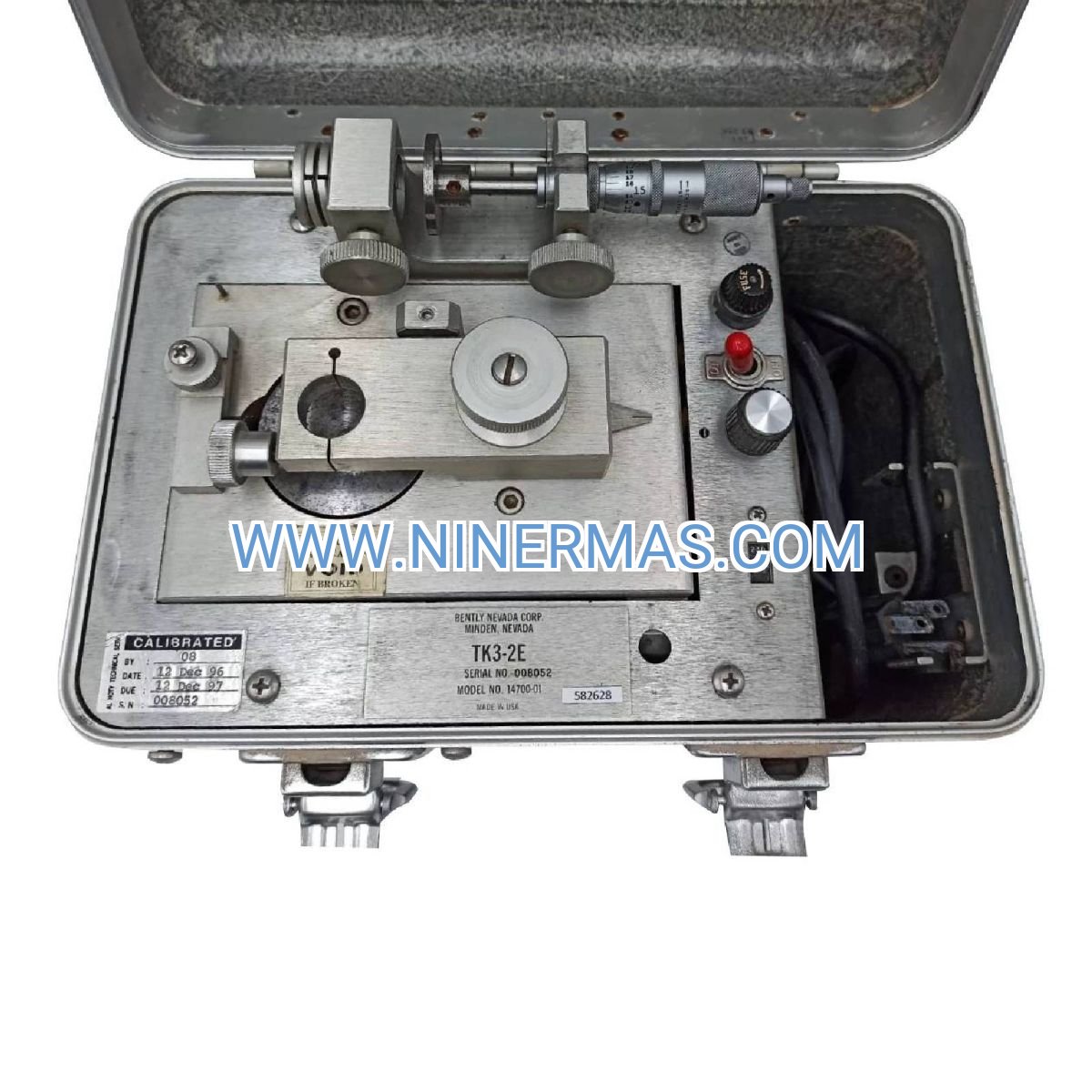

Contact Info
-
Address:22 / F, South Wo Hang building, 148 Wing Lok Street, Sheung Wan, Western District, Hong Kong
-
Phone:+8618750215667
-
Email: