Description
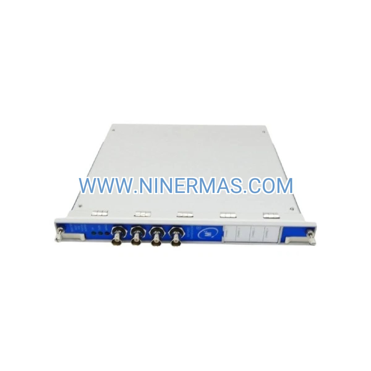
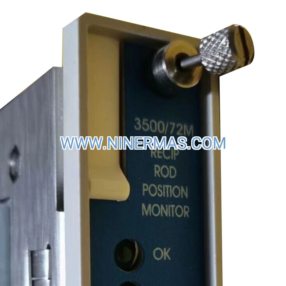
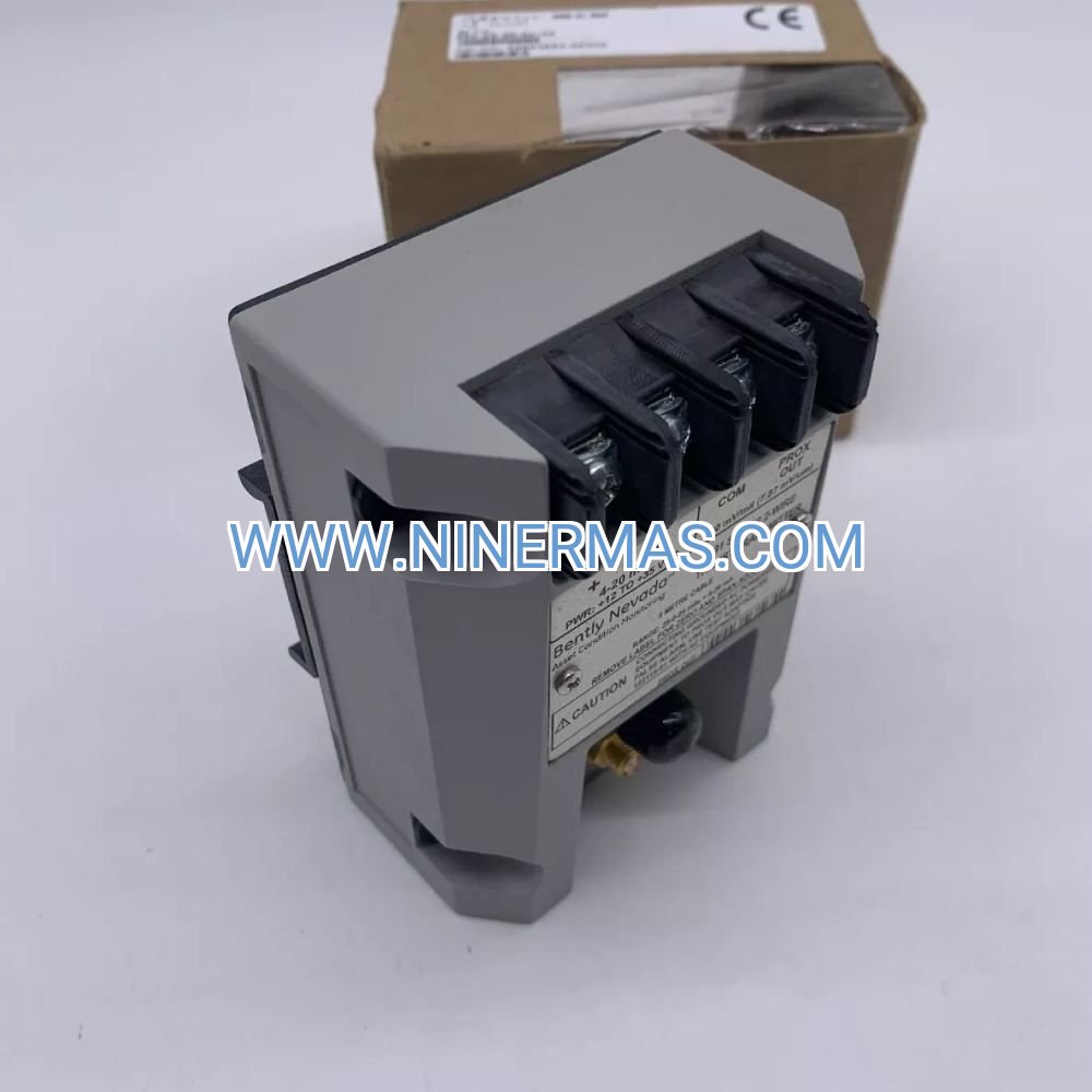
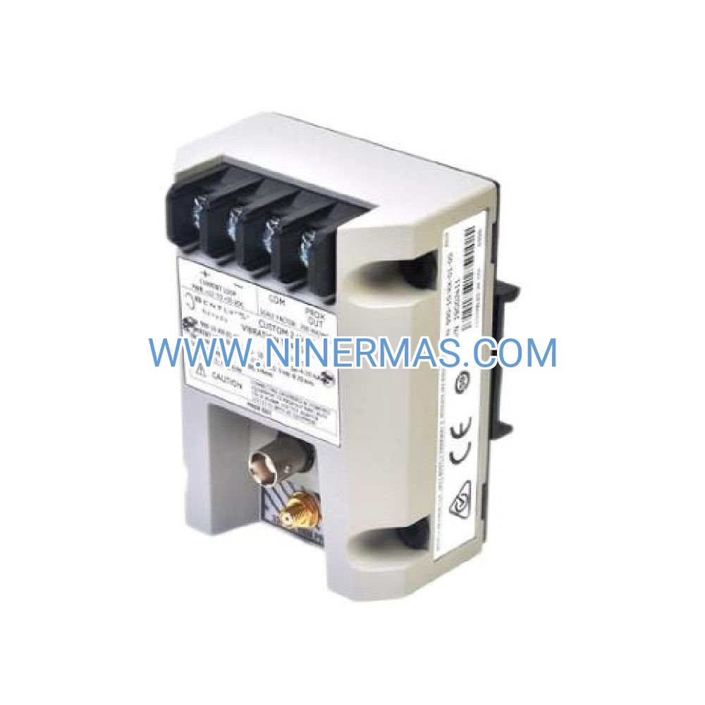
Bently Nevada 140734-08 Proximitor I/O Module (Industrial-Grade 4-Channel Vibration Monitoring Interface)
The Bently Nevada 140734-08 Proximitor I/O Module is a precision signal conditioning interface designed for proximity transducer-based vibration and shaft position monitoring in critical rotating machinery. Through advanced buffering technology and multi-channel architecture, it delivers real-time gap voltage conversion, enabling continuous surveillance of turbines, compressors, motors, and high-speed rotating equipment within the 3500 machinery protection ecosystem.
Engineered for power generation facilities, petrochemical plants, oil & gas processing units, and heavy industrial manufacturing environments, this module addresses challenges including signal degradation over long cable runs, electromagnetic interference from variable frequency drives, transducer power supply instability, and the need for simultaneous data acquisition across multiple monitoring systems. It serves reliability engineers, instrumentation technicians, condition monitoring specialists, and plant maintenance teams requiring API 670-compliant vibration measurement solutions.
Built on proven Bently Nevada technology with hot-swappable capability, EMI/RFI hardened construction, and dual buffered outputs per channel, the 140734-08 ensures measurement accuracy, system uptime, and seamless integration with existing 3500 rack infrastructure. Contact our application engineers with your machinery specifications, probe configuration, and monitoring objectives for customized selection guidance and technical quotations.
Core Functions & Technical Advantages
Precision Signal Conditioning & Buffering
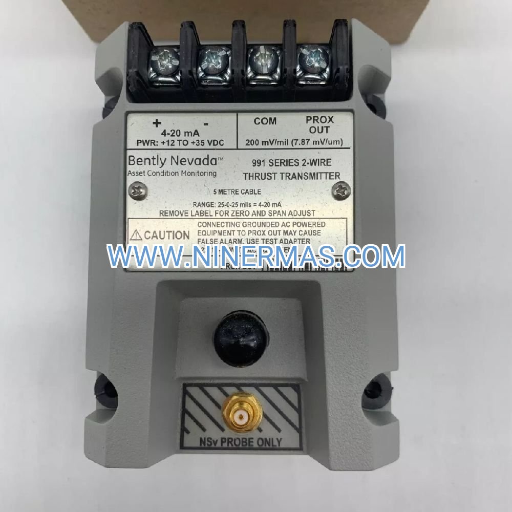
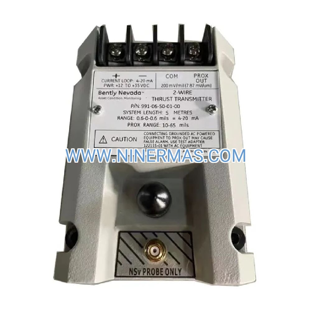
Converts raw proximity probe signals (-24 VDC proximitor output) into standardized buffered voltage outputs (-10 VDC to -2 VDC proportional to target gap), maintaining linear scale factors of 200 mV/mil (7.87 mV/μm) across the full measurement range. Eliminates signal loading effects when connecting to multiple monitoring devices simultaneously.
Multi-Channel Architecture for Comprehensive Coverage
Provides four independent transducer input channels within a single rack slot, reducing hardware footprint by 75% compared to single-channel legacy modules. Each channel operates autonomously with isolated power supplies and dedicated status indicators, preventing cross-channel interference in multi-probe installations.
Wide Frequency Response for Dynamic Event Capture
DC to 10 kHz bandwidth (-3 dB point) captures both slow-roll shaft position changes and high-frequency vibration phenomena including blade-pass frequencies, gear mesh harmonics, and bearing defect signatures. Enables comprehensive spectral analysis from sub-synchronous instabilities to ultrasonic bearing noise.
Integrated Transducer Power & Protection
Supplies regulated -24 VDC power to up to four proximity transducers with individual short-circuit protection and current limiting. Automatic fault isolation prevents single transducer failures from compromising entire monitoring channels, maintaining system availability during component degradation.
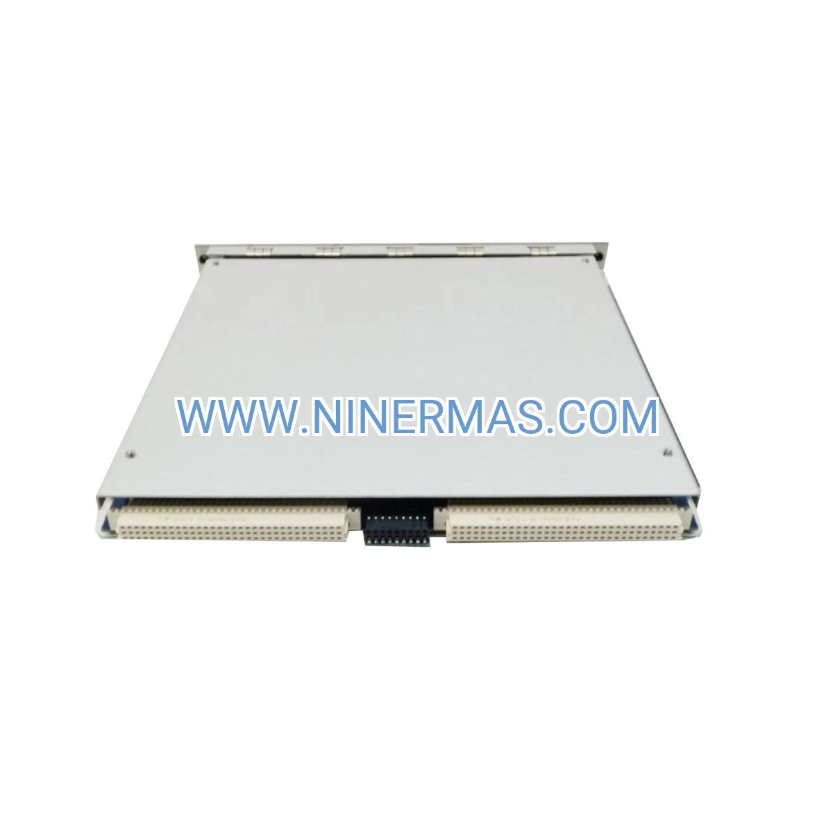
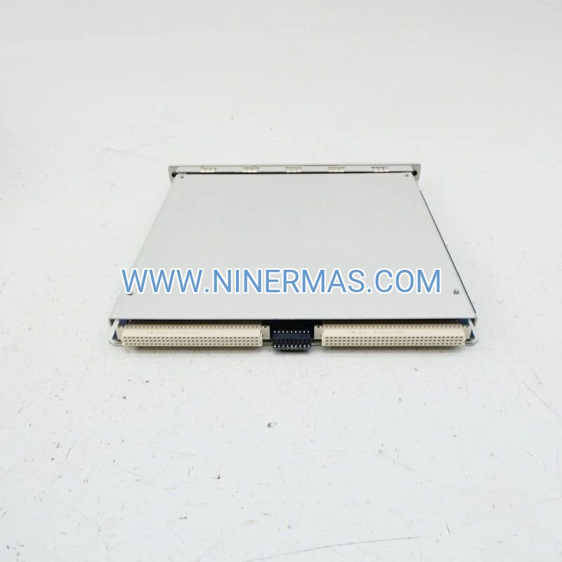
Hot-Swappable Field Serviceability
Front-accessible module design with keyed connectors allows replacement during operation without rack power-down or system reconfiguration. Reduces mean time to repair (MTTR) from hours to minutes during critical maintenance windows, supporting continuous operation requirements in 24/7 process facilities.
Industrial-Grade Environmental Hardening
Military-specification EMI/RFI shielding withstands electromagnetic fields up to 200 V/m, ensuring reliable operation adjacent to motor control centers, VFD cabinets, and high-voltage switchgear. Operating temperature range of -30°C to +65°C accommodates outdoor installations and non-climate-controlled equipment rooms.
Typical Application Scenarios
This module serves industries and applications demanding continuous vibration surveillance and shaft position tracking for asset protection and regulatory compliance:
Steam & Gas Turbine Generator Sets
Monitors radial vibration at journal bearings and axial displacement at thrust bearings in utility-scale power generation units (50 MW to 1000+ MW). Detects rotor unbalance, misalignment, bearing wear, and thrust collar degradation before catastrophic failure. Typical installations include HP/IP/LP turbine sections and generator drive/non-drive ends with 8-12 proximity probes per train.
Centrifugal & Axial Compressor Trains
Tracks shaft vibration amplitude and phase in multi-stage compressors serving natural gas pipelines, LNG liquefaction, air separation plants, and refinery hydrogen units. High-frequency response captures aerodynamic instabilities (surge, rotating stall) and mechanical issues (rub, looseness) that threaten process continuity and equipment integrity.
Critical Process Pumps & Motors
Provides continuous monitoring for boiler feed pumps, charge pumps, cooling water pumps, and large induction motors (>500 HP) where unplanned downtime results in production losses exceeding $50,000 per hour. Enables condition-based maintenance strategies that extend bearing life by 40-60% through early fault detection.
Industrial Fans & Blowers
Monitors induced draft fans, forced draft fans, and process blowers in power plants, cement kilns, and steel mills. Detects fan wheel imbalance, shaft misalignment, and bearing degradation caused by thermal cycling, corrosive atmospheres, and abrasive particulate loading.
Rotating Equipment in Hazardous Areas
When paired with 3300 XL NSv proximity probes (ATEX/IECEx certified), supports installations in Zone 1/Division 1 classified locations including offshore platforms, chemical reactors, and solvent recovery systems. Maintains intrinsic safety barriers while delivering full diagnostic capability.
Technical Parameters & Selection Guide
To facilitate engineering design and procurement, we provide standardized specifications and application-specific configuration options:
| Parameter | Specification |
|---|---|
| Part Number | 140734-08 |
| Input Channels | 4 independent proximity transducer inputs |
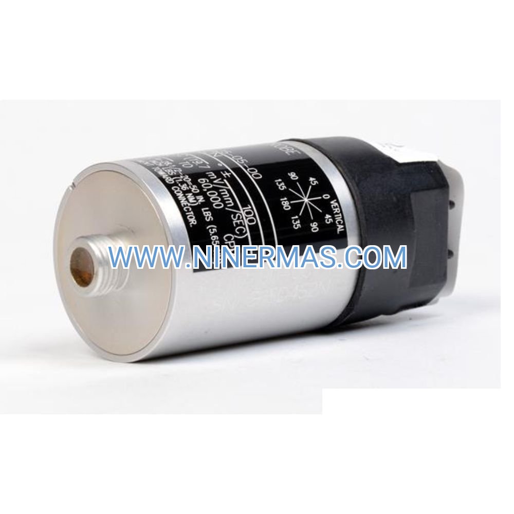
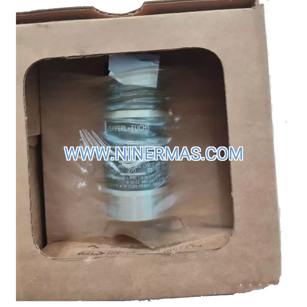
| Compatible Probes | 7200 Series, 3300 XL NSv, 3300 XL 8mm, 3300 XL 11mm |
| Transducer Power Supply | -24 VDC ±5%, 30 mA per channel maximum |
| Output Signal Type | Buffered voltage, -10 VDC to -2 VDC (gap proportional) |
| Outputs Per Channel | 2 buffered outputs (monitor + recorder) |
| Scale Factor | 200 mV/mil (7.87 mV/μm) typical |
| Frequency Response | DC to 10 kHz (-3 dB) |
| Linearity Error | ±1% of full scale over operating range |
| Operating Temperature | -30°C to +65°C (-22°F to +149°F) |
| Storage Temperature | -40°C to +85°C (-40°F to +185°F) |
| Humidity Tolerance | 5% to 95% RH, non-condensing |
| Power Consumption | 4.5W maximum (from 3500 rack backplane) |
| Module Dimensions | Single-slot 3500 rack module (1.6" × 10.5" × 9.0") |
| Weight | 0.9 kg (2.0 lbs) approximate |
| Compliance Standards | API 670 5th Edition, ISO 20816, CE marked |
| MTBF Rating | >200,000 hours (MIL-HDBK-217F) |
Selection Recommendations
When specifying the 140734-08 module, consider the following application parameters: number of proximity probes required (1-4 per module), probe type and cable length (affects system capacitance), monitoring system architecture (standalone 3500 rack vs. integrated DCS), environmental conditions (temperature extremes, EMI sources), and maintenance philosophy (online replacement capability). For systems requiring more than 4 channels, multiple modules can be installed in the same rack with shared power supplies and communication gateways.
Our application engineers can assist with probe selection, cable routing design, rack configuration optimization, and alarm setpoint determination based on machinery API standards and OEM recommendations. Provide equipment type, operating speed range, bearing configuration, and existing instrumentation details for tailored recommendations.
System Integration & Compatibility
The 140734-08 module functions as the front-end interface within a complete 3500 machinery protection system, working in conjunction with:
Monitor Modules: Pairs with 3500/40M Proximitor Monitors (4-channel) or 3500/42M Proximitor/Seismic Monitors (4-channel) that perform signal processing, spectral analysis, alarm logic, and relay outputs. Monitor modules receive buffered signals from the I/O module and execute user-configured protection algorithms.
Rack Infrastructure: Installs in standard 3500 racks (14-slot or 19-slot configurations) with 3500/15 AC or DC power supplies, 3500/20 Rack Interface Modules for communication, and optional 3500/92 Communication Gateways for Modbus TCP/Ethernet connectivity to plant SCADA/DCS systems.
Proximity Probe Systems: Requires complete transducer assemblies including 3300 XL proximity probes, extension cables (330130 series), and proximitor housings or I/O module direct connection. Total system capacitance (probe + cable) must remain within transducer specifications (typically <5000 pF) to maintain calibration accuracy.
Configuration Software: Programmed using 3500 Rack Configuration Software (version 6.x or later) via serial or Ethernet connection. Software allows channel assignment, scaling factor adjustment, output verification, and diagnostic testing without hardware changes.
Data Acquisition Systems: Buffered outputs connect to trending recorders, data historians (OSIsoft PI, GE Proficy), portable analyzers (CSI 2140, SKF Microlog), and third-party condition monitoring platforms for long-term trending and advanced diagnostics.
Installation & Commissioning Considerations
Successful deployment requires attention to mechanical installation, electrical connections, and system verification:
Rack Mounting: Insert module into any available slot in the 3500 rack, ensuring proper seating of backplane connectors. Modules are keyed to prevent incorrect insertion. Secure front panel screws to maintain EMI shielding integrity.
Transducer Wiring: Connect proximity probe extension cables to front-panel terminal blocks using 18-22 AWG shielded twisted-pair wire. Maintain shield continuity to rack ground. Observe polarity markings to ensure correct -24 VDC power delivery and signal return paths.
Output Connections: Route buffered output signals to monitor modules or external recorders using shielded cable with maximum length of 300 meters (1000 feet). Terminate unused outputs with 10 kΩ resistors to ground to minimize noise pickup.
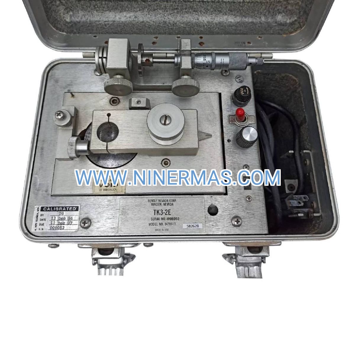
System Verification: After installation, perform end-to-end calibration checks using a precision gap simulator (TK-3 or TK-3E) to verify scale factors, linearity, and output voltage ranges. Confirm OK LED illumination for all channels with connected transducers.
Documentation: Record module serial numbers, channel assignments, probe locations, cable routing, and calibration data in plant asset management systems. Maintain as-built drawings showing transducer positions on machinery and signal flow to monitoring systems.
Frequently Asked Questions (FAQ)
Q: What distinguishes the 140734-08 from other Proximitor I/O module variants in the 3500 series?
A: The -08 suffix denotes a specific firmware revision and output configuration optimized for compatibility with both legacy 3500 monitors and newer 3500M series modules. This variant provides standard buffered outputs with 200 mV/mil scaling, making it suitable for retrofit applications and new installations. Always verify compatibility with your existing rack configuration and monitor module firmware versions.
Q: Can the 140734-08 module interface with 3300 XL NSv (Next-generation Sensor with Verification) proximity probes?
A: Yes, the module fully supports 3300 XL NSv probes, which offer enhanced self-diagnostics, extended temperature ratings, and ATEX/IECEx certifications for hazardous area installations. The NSv probe's verification feature allows in-situ health checks without machinery shutdown, complementing the module's hot-swap capability for maximum system availability.
Q: How should I interpret the OK LED status indicators on each channel?
A: Green LED illumination indicates normal operation with valid transducer connection and gap voltage within acceptable range (typically -2 VDC to -10 VDC). Red LED or no illumination signals fault conditions including open circuit (broken cable), short circuit (damaged transducer), or out-of-range gap voltage (probe too close or too far from target). Consult the 3500 System Manual (Part 141535-01) for detailed troubleshooting flowcharts and corrective actions.
Q: What cable specifications are required for proximity transducer connections to maintain measurement accuracy?
A: Use Bently Nevada factory-terminated extension cables (330130 series) or equivalent shielded twisted-pair cables with capacitance ≤1000 pF per meter and resistance ≤50 Ω per 300 meters. Total system capacitance (probe + extension cable + I/O module input) must not exceed the transducer's maximum rated capacitance (typically 5000 pF for 3300 XL probes) to prevent scale factor shifts and frequency response degradation. Avoid running transducer cables in the same conduit as power cables or VFD wiring.
Q: Is field calibration necessary after replacing a 140734-08 module during maintenance?
A: No, each module ships with factory calibration traceable to NIST standards, and calibration data is stored in non-volatile memory. However, we recommend performing system verification using a calibrated gap simulator after module replacement to confirm end-to-end measurement accuracy including probe, cable, and monitor module. This verification ensures that total system error remains within API 670 requirements (typically ±5% of reading).
Q: Can the 140734-08 module operate in outdoor or high-vibration environments?
A: Yes, the module is designed for industrial environments with operating temperature range of -30°C to +65°C and conformal coating on circuit boards for humidity and contaminant resistance. When installed in a properly sealed 3500 rack enclosure (NEMA 4/IP65 or higher), the system can withstand outdoor installations, high-vibration areas (up to 2g continuous), and corrosive atmospheres. Ensure rack cooling fans and air filters are maintained to prevent internal temperature excursions.
Delivery, Service & Quality Assurance
Lead Times: Standard 140734-08 modules typically ship from stock within 3-5 business days. Custom configurations with special firmware or testing requirements may require 2-3 weeks. Expedited shipping options available for emergency replacements and critical outage support.
Warranty Coverage: All modules include a comprehensive 12-month warranty covering manufacturing defects, component failures, and performance deviations from published specifications. Warranty includes advance replacement service to minimize downtime during critical maintenance windows. Extended warranty programs (24-36 months) available for large-scale installations and multi-year projects.
Technical Support: Our application engineering team provides pre-sale consultation for system design, post-sale commissioning assistance (remote or on-site), and ongoing troubleshooting support. Services include rack configuration file review, alarm setpoint optimization, integration with third-party systems, and operator training.
Documentation Package: Each module ships with installation instructions, wiring diagrams, terminal block layouts, and calibration certificates. Complete system documentation including 3500 Rack Configuration Software, user manuals (PDF format), and API 670 compliance declarations available for download or provided on USB drive upon request.
Quality Certifications: Manufactured under ISO 9001:2015 quality management systems with full traceability of components and production lot codes. Modules undergo 100% functional testing including frequency response verification, output linearity checks, and environmental stress screening per MIL-STD-810G protocols before shipment.
Request Selection Assistance & Quotation
To receive customized selection recommendations, technical specifications, and pricing for your specific application, please provide the following information to our engineering team:
- Project Name & Location: Facility name, equipment tag numbers, geographic location
- Machinery Type: Turbine, compressor, motor, pump, fan (include manufacturer and model if available)
- Operating Parameters: Rated speed (RPM), power output, bearing types, shaft diameter
- Monitoring Requirements: Number of measurement points, probe types currently installed or planned, existing 3500 rack configuration
- Environmental Conditions: Ambient temperature range, indoor/outdoor installation, EMI sources nearby
- Integration Needs: Connection to DCS/SCADA systems, data historian requirements, alarm relay outputs
- Timeline: Project schedule, commissioning date, delivery requirements
Our application engineers will respond within 24 hours with tailored recommendations, system architecture diagrams, and detailed quotations including modules, accessories, and optional services.
© 2026 NINERMAS COMPANY LIMITED. All rights reserved.
Original Source: https://ninermas.com
Contact: sale@ninermas.com | +0086 187 5021 5667

Contact Info
-
Address:22 / F, South Wo Hang building, 148 Wing Lok Street, Sheung Wan, Western District, Hong Kong
-
Phone:+8618750215667
-
Email: