Original Industrial Spare Part
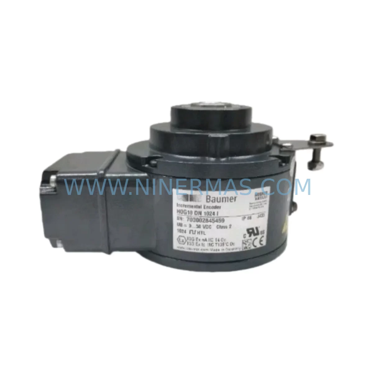
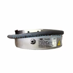
Baumer HOG10DN1024I Retrofit-Compatible Encoder for Legacy Systems
Verify the part, confirm the platform family, and move straight into quotation with the right commercial details.
RFQ Ready
- SKUHOG10DN1024I
- CategoryPLC & Industrial Automation Modules
- BrandBaumer
- SupportAvailability, lead time, condition, and shipping coordination
How Buyers Usually Use This Page
- Confirm the exact part number and platform family before sending the quote request.
- Use direct email when quantity, condition, and destination are already defined internally.
- Switch to the broader brand or category archive when you need alternates nearby.
Series Navigation
Move through the most common platform families behind this part.
Product RFQ
Send this part directly for quotation.
Include quantity, required condition, destination country, and target delivery timing. Current reference: Baumer HOG10DN1024I Retrofit-Compatible Encoder for Legacy Systems with SKU HOG10DN1024I.
Baumer HOG10DN1024I Retrofit-Compatible Encoder for Legacy Systems: Seamless Compatibility and Smooth Upgrade
The Baumer HOG10DN1024I is a high-resolution incremental rotary encoder from the HOG10D series, purpose-built for demanding industrial environments where legacy system continuity is critical. As automation engineers face the growing challenge of maintaining aging control architectures — from obsolete PLCs and discontinued motion controllers to end-of-life servo drives — the HOG10DN1024I provides a reliable, drop-in retrofit solution that minimizes engineering risk and reduces unplanned downtime.
With 1024 pulses per revolution, robust flange mounting, and industry-standard HTL/push-pull signal output, this encoder is engineered to integrate directly into existing control cabinets and machine frames without requiring mechanical redesign. Whether you are replacing a failed encoder on a legacy production line, upgrading a motion axis on an older CNC machine, or migrating a packaging system from an obsolete encoder platform, the HOG10DN1024I delivers the signal integrity and dimensional compatibility your retrofit demands.
Upgrade Compatibility Table
| Parameter | HOG10DN1024I Specification | Retrofit / Legacy Consideration |
|---|---|---|
| Resolution | 1024 PPR | Direct match for most legacy 1024 PPR encoder applications |
| Output Signal | HTL Push-Pull (A, B, Z channels) | Compatible with standard PLC high-speed counter inputs and legacy motion controllers |
| Supply Voltage | 10–30 VDC | Verify existing cabinet power supply capacity; compatible with 24 VDC control systems |
| Shaft / Flange | 10 mm solid shaft, synchro flange | Confirm shaft coupling and flange bore dimensions before installation |
| Connector / Cable | M23 connector or cable exit | Check existing wiring harness; adapter cables available for M12 or terminal block termination |
| Operating Temperature | -20°C to +85°C | Suitable for most industrial panel and machine environments |
| Protection Rating | IP65 | Adequate for standard machine tool and conveyor retrofit applications |
| Mounting Compatibility | Standard synchro / servo flange | Verify backplate clearance and installation space in existing control cabinet or machine frame |
| Communication Protocol | Incremental TTL/HTL pulse train | No protocol migration required; direct wiring to existing counter or drive input |
| Replacement Recommendation | HOG10D series, HOG10DN variants | Confirm original SKU and pulse count before ordering |
| Commissioning Focus | Zero pulse alignment, direction check | Verify Z-pulse reference position and rotation direction in drive or PLC parameters |
| Warranty | 12 Months | Covered from date of shipment; includes pre-shipment functional test |
Retrofit Planning for Existing Automation Systems
Successful encoder retrofit projects begin well before the replacement unit arrives on site. When integrating the Baumer HOG10DN1024I into an existing automation system, engineers must systematically audit the surrounding control architecture to avoid compatibility gaps that cause commissioning delays.
Start with the power supply assessment. The HOG10DN1024I operates across a 10–30 VDC range, making it compatible with the 24 VDC distributed power rails common in Siemens S7-300 and S7-400 control cabinets, as well as older Allen-Bradley SLC 500 and MicroLogix installations. Confirm that the existing 24 VDC power supply module — such as a Siemens SITOP PSU100S or equivalent — has sufficient residual capacity to support the encoder’s current draw alongside other connected field devices.
Next, evaluate the terminal wiring and signal routing. The HOG10DN1024I’s A, B, and Z channel outputs must be correctly mapped to the high-speed counter input terminals of the connected PLC or motion controller. In systems using a Siemens FM 350-1 or FM 350-2 counter module, verify the input filter settings and counting mode configuration match the encoder’s output frequency at maximum shaft speed. For installations using a Beckhoff EL5101 or EL5151 incremental encoder interface terminal, confirm the terminal’s input voltage range is set to HTL mode before connecting the HOG10DN1024I.
Backplane and rack space must also be confirmed. In modular PLC systems — such as those built around a Siemens ET 200M distributed I/O station or a Rockwell 1756 ControlLogix chassis — the counter or encoder interface module occupies a defined slot. Ensure the rack has an available slot adjacent to the existing I/O modules, and that the backplane communication bus supports the counter module’s data exchange rate without introducing scan time penalties.
Module addressing and program compatibility are equally critical. After physical installation, update the hardware configuration in the engineering software — whether STEP 7, TIA Portal, or Studio 5000 — to reflect the new encoder interface module address. Review the existing ladder logic or function block diagram for any encoder-dependent position calculations, cam switching routines, or electronic gearing functions that reference the original encoder’s pulse count or scaling factor. Adjust the position scaling parameters to match the HOG10DN1024I’s 1024 PPR resolution if the original encoder had a different pulse count.
HMI screen updates may also be required. If the machine’s operator panel — such as a Siemens TP700 Comfort or a Weintek MT8000 series HMI — displays position values derived from the encoder feedback, verify that the scaling tags and engineering unit conversions in the HMI project reflect the new encoder parameters. Failure to update HMI scaling can result in incorrect position displays that mislead operators during post-retrofit commissioning.
Finally, confirm the communication link integrity between the encoder interface module and the motion controller or drive. In systems where the encoder signal is routed through a signal isolator or a frequency-to-analog converter before reaching the drive, verify that the isolator’s input frequency range accommodates the HOG10DN1024I’s maximum output frequency. Signal isolators from Phoenix Contact or Weidmüller commonly used in legacy panel builds may require input range reconfiguration when the encoder PPR or shaft speed changes.
Downtime Control During System Migration
Minimizing production downtime during an encoder retrofit requires a structured pre-commissioning strategy. Before removing the failed or obsolete encoder, document the existing wiring connections with photographs and terminal labels. Record the current PLC parameter values for encoder resolution, counting direction, and zero reference position so they can be restored or adjusted after the HOG10DN1024I is installed.
Where possible, perform a bench test of the HOG10DN1024I before the scheduled maintenance window. Connect the encoder to a portable 24 VDC power supply and verify the A, B, and Z channel outputs using an oscilloscope or a dedicated encoder tester. Confirm the pulse count per revolution matches the expected 1024 PPR and that the Z pulse fires once per revolution at a consistent angular position. This pre-shipment functional verification — which is included as part of NINERMAS’s outgoing quality check — significantly reduces the risk of discovering a wiring or configuration fault during a live production stoppage.
During the physical swap, protect the original program logic by placing the PLC in STOP mode and enabling the CPU’s memory protection function before disconnecting any field wiring. This preserves the existing program in the CPU’s retentive memory and prevents accidental overwrite during the hardware reconfiguration. After installing the HOG10DN1024I and reconnecting the terminal wiring, perform a controlled jog of the axis at reduced speed to verify encoder direction and Z-pulse alignment before returning the machine to automatic mode.
For systems where continuous process control is required, consider a phased migration approach: install the HOG10DN1024I in parallel with the existing encoder using a signal splitter, validate the new encoder’s output against the original signal, and then cut over to the new encoder during a planned micro-stoppage. This approach is particularly effective in web tension control systems, winding machines, and printing lines where even brief position feedback interruptions can cause product defects or web breaks.
Retrofit Support FAQ
Q1: Is the HOG10DN1024I a direct replacement for other HOG10D series encoders with different pulse counts?
The HOG10DN1024I is dimensionally and electrically compatible with other HOG10D series variants, but the 1024 PPR resolution is specific to this model. If your original encoder had a different pulse count — such as 500, 2048, or 4096 PPR — you must update the encoder resolution parameter in your PLC, drive, or motion controller after installation. Failure to do so will result in incorrect position scaling and speed feedback errors. Confirm the original SKU and pulse count from the machine documentation or nameplate before ordering.
Q2: What wiring changes are required when replacing a legacy encoder with the HOG10DN1024I?
The HOG10DN1024I uses a standard A, B, Z incremental output with HTL push-pull signal levels. In most legacy installations, the existing shielded encoder cable can be reused if the connector type matches the M23 interface. If the original encoder used a different connector — such as a D-sub 15-pin or a terminal block exit — an adapter cable or field-wireable connector will be required. Always verify the cable shield is connected to the control cabinet earth at a single point to prevent ground loop interference in the encoder signal.
Q3: How is the HOG10DN1024I tested before shipment, and what does the 12-month warranty cover?
Every HOG10DN1024I supplied by NINERMAS undergoes a pre-shipment functional test that verifies pulse output integrity, supply current draw, and mechanical rotation smoothness. The 12-month warranty covers manufacturing defects and functional failures under normal operating conditions from the date of shipment. It does not cover damage resulting from incorrect installation, overvoltage, or mechanical overload. Warranty claims are supported by NINERMAS’s technical team at sale@ninermas.com.
Q4: Can NINERMAS confirm stock availability and lead time before I place an order?
Yes. NINERMAS maintains inventory of the HOG10DN1024I and other HOG10D series encoders to support urgent retrofit and breakdown replacement requirements. Contact our sales team at sale@ninermas.com or +0086 187 5021 5667 to confirm current stock levels, lead time, and shipping options to your location. For critical production line breakdowns, same-day quotation and expedited dispatch are available.
| Product Series | Legacy |
|---|
Catalog Continuation
More Baumer modules in the catalog.
Use the brand lane to compare nearby part numbers, platform-adjacent modules, and other inquiry-ready listings before sending your final RFQ.
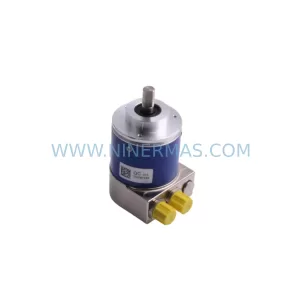
SKU: GXMMW.A202PA2
Baumer GXMMW.A202PA2 Service-Ready Industrial Spare Part
Catalog Continuation
Alternative parts within PLC & Industrial Automation Modules.
Stay inside the same system family when you need substitutes, adjacent modules, or a broader shortlist for procurement review.