Original Industrial Spare Part
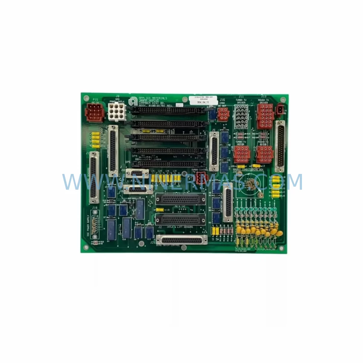
AMAT 0100-01781 Retrofit-Compatible Distribution Module
Verify the part, confirm the platform family, and move straight into quotation with the right commercial details.
RFQ Ready
- SKU0100-01781 0010-10521 AJ530FT-336-B4
- CategoryPLC & Industrial Automation Modules
- BrandApplied Materials (AMAT)
- SupportAvailability, lead time, condition, and shipping coordination
How Buyers Usually Use This Page
- Confirm the exact part number and platform family before sending the quote request.
- Use direct email when quantity, condition, and destination are already defined internally.
- Switch to the broader brand or category archive when you need alternates nearby.
Series Navigation
Move through the most common platform families behind this part.
Product RFQ
Send this part directly for quotation.
Include quantity, required condition, destination country, and target delivery timing. Current reference: AMAT 0100-01781 Retrofit-Compatible Distribution Module with SKU 0100-01781 0010-10521 AJ530FT-336-B4.
AMAT 0100-01781 Retrofit-Compatible Distribution Module: Legacy System Compatibility and Smooth Upgrade Path
The AMAT 0100-01781 (AJ530FT-336-B4) is a ruggedized distribution module originally designed for Applied Materials semiconductor process equipment platforms. As production lines age and original spare parts reach end-of-life status, maintenance engineers and system integrators increasingly rely on retrofit-compatible replacements to sustain uptime without committing to full platform overhauls. This module serves as a direct functional replacement within legacy AMAT equipment architectures, supporting power distribution, signal routing, and backplane interfacing in harsh cleanroom and industrial environments.
When planning a retrofit around the 0100-01781, engineers must first audit the existing backplane slot assignment and verify that the replacement module’s connector pinout matches the original installation. The AJ530FT-336-B4 designation identifies a specific revision level; confirming this revision against the equipment’s BOM (Bill of Materials) prevents compatibility mismatches during installation. Power rail capacity — typically 24 VDC or 48 VDC depending on the sub-system — must be validated before energizing the replacement unit. Terminal block wiring diagrams from the original equipment manual should be cross-referenced to ensure signal polarity and ground continuity are preserved.
In many legacy AMAT platforms, the 0100-01781 operates alongside companion modules such as the AMAT 0100-01782 (an adjacent distribution board sharing the same backplane segment) and the AMAT 0100-00927 (a power conditioning module that feeds regulated voltage to the distribution layer). When either of these modules is also flagged for replacement, it is strongly recommended to perform a coordinated swap during the same maintenance window to avoid repeated system shutdowns. The AMAT 0100-09054 interconnect cable assembly is frequently required to re-terminate signal paths after a distribution module exchange, and stock of this cable should be confirmed before scheduling the outage.
Upgrade Compatibility Table
| Parameter | Original / Legacy | AMAT 0100-01781 (AJ530FT-336-B4) |
|---|---|---|
| Module Form Factor | Ruggedized PCB Assembly | Ruggedized PCB Assembly — direct form-fit replacement |
| Backplane Interface | AMAT proprietary edge connector | Compatible with original backplane slot; verify revision suffix |
| Power Input | 24 VDC / 48 VDC (platform-dependent) | Matches original rail; confirm with equipment power distribution schematic |
| Signal Compatibility | Analog and digital I/O per original BOM | Preserved; no firmware change required for direct swap |
| Installation Space | Standard AMAT module bay | Same physical envelope; no mechanical modification needed |
| Communication Link | Internal backplane bus | Fully compatible; no protocol migration required |
| Commissioning Requirement | Address configuration via equipment controller | Verify module address assignment matches original slot mapping |
| Warranty | OEM warranty expired (EOL part) | 12-Month Warranty from NINERMAS — covers functional defects post-installation |
Retrofit Planning for Existing Automation Systems
A successful retrofit of the AMAT 0100-01781 begins well before the physical swap. The first step is a full documentation review: pull the equipment’s wiring diagram, the backplane layout drawing, and the module address map from the controller configuration. In AMAT platforms, the equipment controller — often a VME-based or proprietary embedded controller — maintains a slot-to-address table that must remain consistent after the module replacement. If the address table is stored in non-volatile memory on the original module, this data must be captured before removal.
Power sequencing is a critical consideration. The AMAT 0100-01365 power sequencer module, where present, controls the order in which sub-systems are energized during startup. Bypassing or incorrectly configuring this sequencer during a distribution module swap can result in inrush current events that damage adjacent boards. Coordinate with the sequencer’s configuration before powering down the affected sub-system.
For systems that include an HMI panel — such as those running on an AMAT 0190-35811 operator interface board — verify that the HMI screen assignments for the distribution module’s status indicators remain valid after the swap. Some legacy HMI configurations reference module slot positions directly; a module replacement that changes the physical slot may require an HMI screen update to restore correct alarm and status display.
Signal isolation is another area requiring attention. Where the 0100-01781 interfaces with external field devices through optocoupled or relay-isolated outputs, the AMAT 0100-90576 signal isolation board may be installed in series. Confirm that the isolation board’s input voltage range is compatible with the replacement module’s output drive level before completing the installation. In some retrofit scenarios, engineers also add a dedicated AMAT 0100-01044 I/O expansion module to the adjacent slot to restore signal capacity that was previously handled by a failed distribution module — this approach avoids the need to reroute field wiring and reduces commissioning time.
Programming cable compatibility should be confirmed if the equipment controller requires re-initialization after the module swap. The AMAT 0100-09054 programming and diagnostic cable, along with the appropriate terminal emulation software, allows engineers to verify module communication status and re-enter configuration parameters without removing the module from the chassis. Having this cable on-site before the maintenance window begins is strongly recommended.
Downtime Control During System Migration
Minimizing production downtime during a distribution module replacement requires a structured pre-outage preparation protocol. Begin by staging all replacement components — including the 0100-01781 module, any required interconnect cables, and spare terminal blocks — at least 24 hours before the scheduled maintenance window. Confirm that the replacement unit has passed pre-shipment functional testing (all NINERMAS-supplied modules undergo bench-level power-on and signal continuity verification before dispatch).
Before de-energizing the affected sub-system, capture a full snapshot of the equipment controller’s current configuration: module addresses, I/O assignments, alarm thresholds, and any calibration offsets stored in the controller’s memory. This snapshot serves as the restoration baseline if the controller requires re-initialization after the swap. Where possible, use the equipment’s built-in diagnostic mode to log the current module status — this provides a pre-swap reference for post-installation verification.
During the physical swap, follow a strict ESD (electrostatic discharge) protocol: use a grounded wrist strap, handle the module by its edges, and avoid contact with exposed connector pins. Seat the replacement module firmly into the backplane slot and verify that all locking mechanisms are engaged before restoring power. After power-up, allow the equipment controller a full initialization cycle before checking module status indicators. Compare the post-swap diagnostic readout against the pre-swap snapshot to confirm that all signal assignments and address mappings have been restored correctly.
If the equipment includes a watchdog or safety interlock circuit that monitors distribution module health, verify that the interlock has cleared before returning the system to production mode. Document the replacement — including the module serial number, installation date, and technician name — in the equipment’s maintenance log to support warranty claims and future audit requirements.
Retrofit Support FAQ
Q1: Is the AMAT 0100-01781 a direct drop-in replacement for the original module, or are modifications required?
The 0100-01781 (AJ530FT-336-B4) is designed as a form-fit-function replacement for the original AMAT distribution module in the same equipment platform. No mechanical modification is required. However, engineers should verify the revision suffix (B4) against the equipment BOM to confirm compatibility, and should re-enter any module address or configuration parameters that are not automatically restored by the equipment controller after the swap.
Q2: What pre-shipment testing does NINERMAS perform on this module?
All AMAT 0100-01781 units supplied by NINERMAS undergo bench-level power-on testing, signal continuity verification, and visual inspection for physical damage before dispatch. A test report is available upon request. Each unit is covered by a 12-month warranty against functional defects from the date of delivery.
Q3: How should terminal wiring be handled during the replacement to avoid signal errors?
Before removing the original module, photograph or document all terminal block wiring connections, including wire labels, colors, and terminal positions. Use the equipment’s original wiring diagram to verify each connection before re-terminating on the replacement module. Pay particular attention to ground continuity and shield termination points, as improper grounding is a common source of signal noise in ruggedized distribution modules operating in harsh environments.
Q4: What is the typical lead time and inventory availability for the AMAT 0100-01781?
NINERMAS maintains reserved inventory of the AMAT 0100-01781 to support urgent maintenance requirements. Standard lead time for in-stock units is 3–7 business days for international shipment. For customers with recurring demand, long-term stock reservation agreements are available to guarantee supply continuity for critical spare parts programs. Contact our team at sale@ninermas.com or +0086 187 5021 5667 to confirm current stock levels and arrange priority dispatch.
| Product Series | Other series |
|---|---|
| Country of Origin | US |
Catalog Continuation
More Applied Materials (AMAT) modules in the catalog.
Use the brand lane to compare nearby part numbers, platform-adjacent modules, and other inquiry-ready listings before sending your final RFQ.
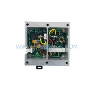
SKU: 0100-09032, 0100-09033 0020-10758 030401-2 NC-95-PP S6ASS5310/292 19436
AMAT 0100-09032 Service-Ready Spare for Industrial Maintenance
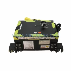
SKU: 0190-15614 10821A 0021-96021 MFA090HA5NSC
AMAT 0190-15614-10821A-0021-96021-MFA090HA5NSC Industrial Spare
Catalog Continuation
Alternative parts within PLC & Industrial Automation Modules.
Stay inside the same system family when you need substitutes, adjacent modules, or a broader shortlist for procurement review.
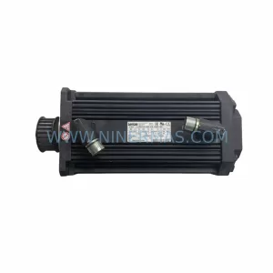
SKU: 14L41-RS0B0-B24R-ST5S00N-R0SU
LENZE 14L41-RS0B0-B24R-ST5S00N-R0SU Retrofit for Legacy Systems
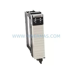
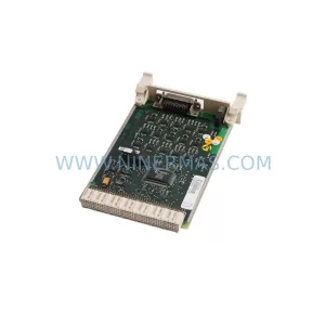
SKU: CI540 3BSE001077R1
ABB CI540 3BSE001077R1 Spare Part for Industrial Maintenance
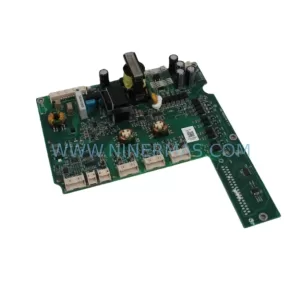
SKU: ZINT-541 3AUA00000658960
ABB ZINT-541 3AUA00000658960 Retrofit-Compatible Inverter Power Module