Original Industrial Spare Part
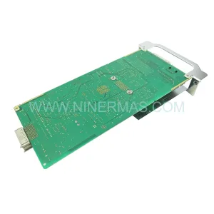
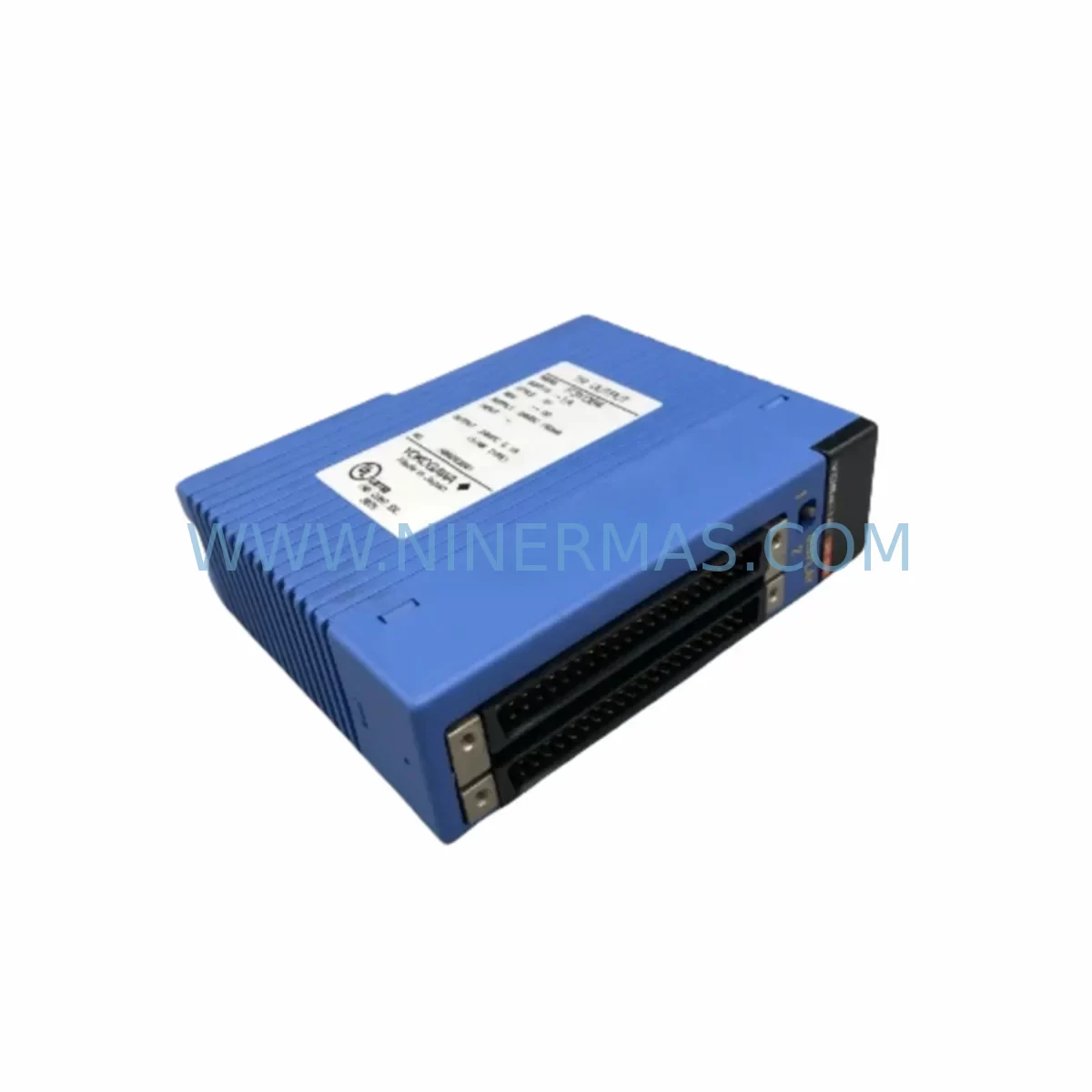
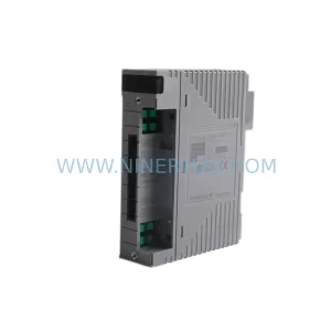
YOKOGAWA F3YD64-1A Retrofit-Compatible Transistor Output Module
Verify the part, confirm the platform family, and move straight into quotation with the right commercial details.
RFQ Ready
- SKUF3YD64-1A
- CategorySIS Safety & Redundancy Systems
- BrandYokogawa
- SupportAvailability, lead time, condition, and shipping coordination
How Buyers Usually Use This Page
- Confirm the exact part number and platform family before sending the quote request.
- Use direct email when quantity, condition, and destination are already defined internally.
- Switch to the broader brand or category archive when you need alternates nearby.
Series Navigation
Move through the most common platform families behind this part.
Product RFQ
Send this part directly for quotation.
Include quantity, required condition, destination country, and target delivery timing. Current reference: YOKOGAWA F3YD64-1A Retrofit-Compatible Transistor Output Module with SKU F3YD64-1A.
YOKOGAWA F3YD64-1A Retrofit-Compatible Transistor Output Module: Legacy System Compatibility and Smooth Upgrade
The YOKOGAWA F3YD64-1A is a 64-point transistor output module designed for the YOKOGAWA FA-M3 programmable controller platform. As production lines age and original equipment manufacturers discontinue legacy I/O modules, the F3YD64-1A has become a critical spare part and retrofit solution for facilities running FA-M3-based control architectures. Whether you are replacing a failed output module on an existing rack, expanding digital output capacity, or migrating from an older FA-M3 configuration to a modernized control cabinet layout, the F3YD64-1A delivers the electrical compatibility and mechanical fit required for a low-risk, minimum-downtime changeover.
Engineered for harsh industrial environments, the F3YD64-1A features ruggedized transistor output circuitry capable of withstanding vibration, temperature variation, and electrical noise common in process manufacturing, discrete assembly, and utilities applications. Its 64-channel NPN transistor output design supports a wide range of field devices including solenoid valves, indicator lamps, relay coils, and motor starters operating at standard 24 VDC load voltages. The module slots directly into FA-M3 base units such as the F3BU04-0N, F3BU16-0N, and F3BU32-0N backplanes without requiring hardware modification, preserving existing wiring harnesses and terminal block layouts.
Upgrade Compatibility Table
| Parameter | F3YD64-1A Specification | Retrofit Notes |
|---|---|---|
| Output Points | 64 points (NPN transistor) | Verify field device polarity before swap |
| Output Voltage | 24 VDC (12–48 VDC range) | Confirm load voltage matches existing wiring |
| Output Current | 0.1 A per point, 2 A per common | Check total common current against load list |
| Backplane Interface | FA-M3 bus connector (standard) | Compatible with F3BU04/16/32 base units |
| Module Address | Set via slot position on base unit | Confirm slot address matches PLC program I/O map |
| Communication Protocol | FA-M3 internal bus | No protocol change required for direct replacement |
| Installation Space | Single-slot FA-M3 module form factor | Verify cabinet rail space and module clearance |
| Wiring Terminal | 40-pin connector (2 × 20) | Retain existing terminal block; re-seat connector |
| Commissioning | Force output test via ToolBox or WideField3 | Run I/O forced test before returning to AUTO |
| Warranty | 12-Month Warranty — All units pre-shipment tested | |
Retrofit Planning for Existing Automation Systems
Replacing the F3YD64-1A within an active FA-M3 control system requires a structured approach that accounts for the full scope of the control cabinet and field wiring. Before initiating the swap, engineers should pull the current I/O assignment list from the WideField3 programming environment and cross-reference each output address against the field device schedule. The F3YD64-1A occupies a single slot on the FA-M3 base unit, and its slot position directly determines the I/O address range allocated in the PLC program — any mismatch between the physical slot and the software address map will result in incorrect output activation during commissioning.
Power supply capacity is a primary concern during retrofit planning. The FA-M3 system power supply module — such as the F3PU20-0S or F3PU30-0S — must have sufficient residual capacity to support the F3YD64-1A’s internal consumption alongside all other installed modules. Review the base unit power budget before insertion, particularly in fully populated 16- or 32-slot racks where power margins may be tight. If the existing power supply is operating near its rated output, consider replacing it concurrently with the output module to avoid nuisance trips after the retrofit.
Terminal block wiring on the F3YD64-1A uses a 40-pin connector that mates with the module’s front-face terminal interface. In most legacy installations, the field wiring is landed on a removable terminal block assembly, which can be disconnected from the old module and re-seated on the replacement unit without re-terminating individual conductors. Verify that the terminal block locking tabs are fully engaged after re-seating to prevent intermittent contact faults under vibration. Where field wiring has been modified or extended since original installation, inspect conductor insulation and confirm that wire ferrules are correctly crimped before reconnection.
For systems that include YOKOGAWA FA-M3 communication modules such as the F3LE01-5T Ethernet interface or the F3LC11-1F FL-net module, confirm that the output module replacement does not affect the communication module’s network address or station configuration. In multi-drop FA-M3 networks where a master controller polls remote I/O stations, the station address is typically set on the communication module rather than the I/O module itself, so a direct F3YD64-1A swap will not disrupt network topology. However, if the retrofit involves relocating the module to a different slot or base unit, update the I/O map in the master PLC program accordingly.
HMI screen updates are often overlooked during output module retrofits. If the facility uses a YOKOGAWA ProSafe-RS safety system or a third-party HMI platform connected to the FA-M3 via Modbus TCP or MELSEC protocol, verify that the output tag addresses referenced in HMI faceplates remain valid after the module swap. In cases where the original module was mapped to a non-standard address offset, the HMI tag database may require a minor revision to reflect the correct output register range. Coordinate with the HMI engineer before returning the system to automatic operation.
Signal isolation requirements should also be reviewed during retrofit planning. Where the F3YD64-1A drives inductive loads such as solenoid valves or relay coils, ensure that flyback suppression diodes or RC snubber circuits are installed at the load terminals. Without adequate suppression, inductive kickback can exceed the module’s output transistor voltage rating and cause premature failure of the replacement unit. In legacy control cabinets where suppression components were not originally fitted, add them during the retrofit to extend the service life of the new module.
Downtime Control During System Migration
Minimizing production downtime during an F3YD64-1A replacement requires advance preparation and a disciplined changeover sequence. Begin by scheduling the swap during a planned maintenance window or shift changeover, and notify all affected production supervisors of the expected outage duration. A direct module replacement on a healthy FA-M3 base unit typically requires 15 to 30 minutes of controlled downtime, provided that the replacement module is on-site, the terminal block is removable, and the I/O address map has been verified in advance.
Before powering down the FA-M3 rack, use WideField3 or the FA-M3 handheld programmer to capture a backup of the current PLC program, including all I/O force tables and data register values. Store the backup on a local engineering workstation and verify the file integrity before proceeding. This backup protects against accidental program loss during the module swap and provides a restore point if the replacement module exhibits unexpected behavior during initial power-up.
After inserting the F3YD64-1A and re-seating the terminal block, power up the FA-M3 rack in STOP mode and use the WideField3 I/O monitor to verify that all 64 output points are recognized by the CPU module — typically an F3SP71-4S or F3SP76-7S processor — before switching to RUN mode. Force each output point individually using the I/O force function and confirm field device response at the terminal before releasing the force. This step-by-step verification prevents uncontrolled actuator movement during the initial RUN transition and confirms that the wiring reconnection is correct across all 64 channels.
For facilities with redundant control architectures or hot-standby FA-M3 configurations, coordinate the module swap with the redundancy switchover procedure to ensure that the standby controller assumes control before the primary rack is de-energized. This approach eliminates process interruption entirely and allows the replacement to be completed without a production stop. After the swap, perform a controlled switchback to the primary controller and monitor the system for at least one full production cycle before closing the maintenance record.
Retrofit Support FAQ
Q1: Is the F3YD64-1A a direct drop-in replacement for the F3YD32-1A or F3YD16-1A?
The F3YD64-1A shares the same FA-M3 module form factor and backplane connector as the F3YD32-1A and F3YD16-1A, but provides 64 output points versus 32 or 16. If you are replacing a lower-density module with the F3YD64-1A, the additional output points will be available in the PLC program but must be assigned to field devices or left unused. Update the I/O assignment list and HMI tag database to reflect the expanded channel count before commissioning.
Q2: What commissioning steps are required after installing the F3YD64-1A?
After physical installation, power up the FA-M3 rack in STOP mode and verify module recognition in WideField3. Use the I/O force function to test each output channel individually and confirm field device response. Check the common current loading against the module’s 2 A per common rating, and verify that flyback suppression is in place on all inductive loads. Switch to RUN mode only after all 64 channels have been verified.
Q3: Does the F3YD64-1A ship pre-tested, and what warranty is provided?
Yes. All F3YD64-1A units supplied by NINERMAS are pre-shipment tested under simulated load conditions to verify output switching performance across all 64 channels. Each unit is covered by a 12-month warranty from the date of shipment. Warranty claims are supported by our technical team at sale@ninermas.com.
Q4: What is the typical lead time and stock availability for the F3YD64-1A?
NINERMAS maintains buffer stock of the F3YD64-1A to support urgent retrofit and breakdown replacement requirements. Standard orders ship within 3–5 business days. For large-quantity orders or long-term supply agreements supporting lifecycle extension programs, contact our procurement team to discuss committed stock arrangements and fixed lead-time contracts.
| Product Series | FA-M3 |
|---|---|
| Country of Origin | JP |
Catalog Continuation
More Yokogawa modules in the catalog.
Use the brand lane to compare nearby part numbers, platform-adjacent modules, and other inquiry-ready listings before sending your final RFQ.
Catalog Continuation
Alternative parts within SIS Safety & Redundancy Systems.
Stay inside the same system family when you need substitutes, adjacent modules, or a broader shortlist for procurement review.