Original Industrial Spare Part
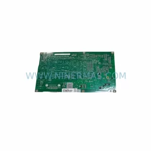
LTI SA54-0550-0033-0000-0 Retrofit Servo Drive Legacy Systems
Verify the part, confirm the platform family, and move straight into quotation with the right commercial details.
RFQ Ready
- SKUSA54.0550.0033.0000.0
- CategoryPLC & Industrial Automation Modules
- BrandLTI Motion
- SupportAvailability, lead time, condition, and shipping coordination
How Buyers Usually Use This Page
- Confirm the exact part number and platform family before sending the quote request.
- Use direct email when quantity, condition, and destination are already defined internally.
- Switch to the broader brand or category archive when you need alternates nearby.
Series Navigation
Move through the most common platform families behind this part.
Product RFQ
Send this part directly for quotation.
Include quantity, required condition, destination country, and target delivery timing. Current reference: LTI SA54-0550-0033-0000-0 Retrofit Servo Drive Legacy Systems with SKU SA54.0550.0033.0000.0.
LTI SA54-0550-0033-0000-0 Retrofit Servo Drive: Legacy-Compatible Upgrade for Existing Automation Systems
The LTI Motion SA54-0550-0033-0000-0 is a high-performance servo drive from the SA54 SystemDrive series, designed for demanding industrial motion control applications. As legacy automation lines age and original spare parts become increasingly difficult to source, the SA54-0550-0033-0000-0 serves as a critical retrofit-compatible replacement for end-of-life servo drive modules in existing control cabinets. Whether you are managing a planned upgrade or responding to an unplanned failure, this unit supports a smooth, low-risk transition with minimal disruption to production continuity.
NINERMAS COMPANY LIMITED maintains verified stock of the SA54-0550-0033-0000-0 and provides full pre-shipment functional testing, ensuring every unit leaves our facility in confirmed working condition. Each unit is covered by a 12-month warranty from the date of delivery.
Upgrade Compatibility Table
| Parameter | SA54-0550-0033-0000-0 Specification | Retrofit Notes |
|---|---|---|
| Series | LTI Motion SA54 SystemDrive | Compatible with SA54 series rack and backplane |
| Rated Output Current | 33 A continuous | Verify existing motor nameplate current rating before replacement |
| DC Bus Voltage | 550 V DC link | Confirm power supply module output matches DC bus specification |
| Communication Interface | SystemBus / SERCOS / optional fieldbus | Verify communication protocol version with existing PLC or CNC controller |
| Installation Format | Modular rack-mount, SA54 backplane | Confirm slot position and backplane connector alignment before installation |
| Encoder Feedback | Resolver / incremental encoder input | Match encoder type and cable pinout to existing motor feedback wiring |
| Cooling | Forced air / internal fan | Ensure cabinet ventilation clearance meets original installation specification |
| Replacement Relationship | Direct replacement for SA54-0550-0033-0000-0 | No firmware modification required for like-for-like swap |
| Commissioning Tool | LTI DriveManager / compatible programming cable | Backup existing drive parameters before replacement; restore after installation |
| Warranty | 12 Months from delivery date | Covered by NINERMAS standard warranty; pre-shipment functional test included |
Retrofit Planning for Existing Automation Systems
Replacing a servo drive in a live production environment requires careful pre-planning across multiple system layers. The SA54-0550-0033-0000-0 is typically installed within a multi-axis SA54 series rack alongside companion modules that must be evaluated as part of any retrofit project.
Before initiating the replacement, engineers should audit the existing power supply module — commonly a CDA34 or CDB34 series unit — to confirm that the DC bus capacity is sufficient to support the replacement drive under peak load conditions. If the power supply module is also approaching end-of-life, sourcing a matched replacement such as the CDA34.006 or CDB34.005 in parallel with the servo drive will reduce the risk of a secondary failure shortly after the initial retrofit is completed.
The backplane and rack assembly must be inspected for connector wear, corrosion, and mechanical damage. In SA54 series installations, the backplane carries both the DC bus and the SystemBus communication signals. A damaged backplane connector can cause intermittent faults that are difficult to diagnose after the new drive is installed. If the rack has been in service for more than ten years, replacing the backplane connector or the full rack assembly should be considered as part of the upgrade scope.
Wiring and terminal adaptation is another critical checkpoint. The SA54-0550-0033-0000-0 uses standard SA54 series terminal layouts for motor power, brake control, and encoder feedback. However, if the existing installation used custom cable assemblies or non-standard pinout adaptors, these must be documented and verified against the replacement unit’s terminal specification before energizing the system. The brake control output — often connected to a CDE34 series brake module — must be confirmed to operate correctly with the replacement drive’s brake release logic.
For systems using SERCOS or SystemBus communication, the module address and node configuration stored in the drive must be re-entered or restored from a parameter backup after the replacement. If the original drive parameters were not backed up prior to failure, the commissioning engineer will need to reconstruct the axis configuration from the machine documentation or from the PLC program’s axis parameter tables. In multi-axis systems, the SA54-0550-0033-0000-0 must be assigned the correct node address to avoid communication conflicts with adjacent axes — which may include other SA54 series drives such as the SA54-0550-0066-0000-0 or SA54-0275-0033-0000-0 installed in the same rack.
HMI screen validation is often overlooked during servo drive replacement. If the machine uses an HMS01 operator panel or a third-party HMI connected via the machine controller, the axis status displays and alarm messages should be verified after commissioning to confirm that the replacement drive is reporting correctly to the HMI. Any axis-specific alarm codes that were previously suppressed or acknowledged in the HMI configuration should be reviewed to ensure they remain valid for the replacement unit.
For I/O-intensive applications, the digital and analog I/O assignments within the drive must be confirmed against the existing PLC program. If the machine uses a distributed I/O architecture with signal isolators between the drive and the field devices, the isolator output ranges and signal conditioning settings should be verified to remain compatible with the replacement drive’s I/O specifications. A mains filter — such as a CDE34.008 series unit — installed upstream of the drive should also be inspected and replaced if it shows signs of degradation, as a failing mains filter can cause nuisance trips on a newly installed drive.
Finally, the programming cable and commissioning software must be confirmed to be compatible with the SA54-0550-0033-0000-0 firmware version. LTI DriveManager or the equivalent commissioning tool should be used to perform a final parameter verification and a test run under no-load conditions before the machine is returned to production.
Downtime Control During System Migration
Minimizing unplanned downtime is the primary objective of any servo drive replacement project. For the SA54-0550-0033-0000-0, the most effective downtime reduction strategy begins before the replacement unit arrives on site.
The first step is to perform a full parameter backup of the existing drive while it is still operational. Using the LTI DriveManager software and a compatible programming cable, all axis parameters, motor data, control loop tuning values, and I/O assignments should be exported and stored in a secure location. This backup eliminates the need for re-tuning after the replacement and significantly reduces commissioning time.
The second step is to prepare a detailed wiring checklist that documents every terminal connection on the existing drive, including motor power cables, encoder feedback cables, brake control wiring, and any fieldbus or SystemBus connectors. Photographs of the existing wiring should be taken before disconnection. This documentation allows the replacement drive to be wired correctly on the first attempt, avoiding the delays caused by wiring errors discovered during the initial power-up.
During the physical swap, the rack slot position must be confirmed before the replacement drive is inserted. In SA54 series multi-axis racks, inserting a drive into the wrong slot can cause immediate faults or damage to the backplane. The replacement SA54-0550-0033-0000-0 should be inserted with the DC bus de-energized and the main circuit breaker locked out in accordance with local electrical safety regulations.
After installation and wiring, the parameter backup should be restored before the first power-up. A no-load test run should be performed to verify that the drive initializes correctly, communicates with the PLC or CNC controller, and responds to motion commands without faults. Only after a successful no-load test should the machine be reconnected to the mechanical load and returned to production.
NINERMAS provides pre-shipment functional testing on all SA54-0550-0033-0000-0 units to confirm that the drive is fully operational before it leaves our facility. This reduces the risk of receiving a non-functional unit and eliminates the additional downtime that would result from a second replacement cycle.
Retrofit Support FAQ
Q1: Is the SA54-0550-0033-0000-0 a direct drop-in replacement for the original LTI Motion unit?
Yes. The SA54-0550-0033-0000-0 is a like-for-like replacement for the original LTI Motion SA54 series servo drive of the same model number. It uses the same backplane connector, the same terminal layout, and the same communication interface as the original unit. No hardware modification is required for a standard replacement. Parameter restoration from a backup file is recommended to minimize commissioning time.
Q2: What commissioning steps are required after installing the replacement drive?
After physical installation and wiring, the following commissioning steps are recommended: (1) Restore the parameter backup from the original drive using LTI DriveManager. (2) Verify the node address and communication settings match the original configuration. (3) Perform a no-load test run to confirm correct initialization and communication with the machine controller. (4) Verify brake control operation and encoder feedback signals. (5) Perform a loaded test run at reduced speed before returning the machine to full production speed.
Q3: Does NINERMAS provide pre-shipment testing and a warranty for this unit?
Yes. Every SA54-0550-0033-0000-0 unit shipped by NINERMAS undergoes a functional test before dispatch to confirm that the drive powers up correctly and operates within specification. All units are covered by a 12-month warranty from the date of delivery. If a unit develops a fault within the warranty period under normal operating conditions, NINERMAS will provide a replacement or repair at no additional cost.
Q4: What should I check if the replacement drive generates a communication fault after installation?
Communication faults after a drive replacement are most commonly caused by one of the following: (1) Incorrect node address — verify that the replacement drive has been assigned the same node address as the original unit. (2) Incorrect baud rate or protocol version — confirm that the SystemBus or SERCOS settings match the controller configuration. (3) Damaged backplane connector — inspect the backplane slot for bent pins or contamination. (4) Parameter mismatch — if the parameter backup was not restored, the drive may be using default communication settings that differ from the machine configuration. Restoring the parameter backup and performing a communication reset on the controller typically resolves these issues.
| Product Series | Other series |
|---|
Catalog Continuation
More LTI Motion modules in the catalog.
Use the brand lane to compare nearby part numbers, platform-adjacent modules, and other inquiry-ready listings before sending your final RFQ.
SKU: LSC-070-3-30-560-P5B0H2MM0
LTi Motion LSC-070-3-30-560-P5B0H2MM0 Retrofit Servo Drive
SKU: LSC-130-3-20-560-A5B2R1PM0M
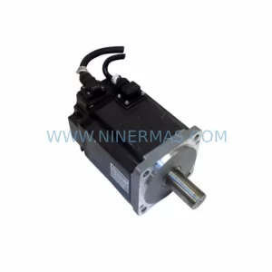
LTI MOTION LSC-130-3-20-560-A5B2R1PM0M Retrofit AC Servo Motor
SKU: LSC-060-3-30-560-P5B0H2MM0
LTI Motion LSC-060-3-30-560-P5B0H2MM0 Safety-Reliable Servo Drive
SKU: LSC-070-2-50-560-P5B0R1PM0
LTI MOTION LSC-070-2-50-560-P5B0R1PM0 Safety-Reliable Servo Drive
Catalog Continuation
Alternative parts within PLC & Industrial Automation Modules.
Stay inside the same system family when you need substitutes, adjacent modules, or a broader shortlist for procurement review.
SKU: 6FC5357-0BB12-0AE0
Siemens 6FC5357-0BB12-0AE0 Service-Ready Industrial Spare Part
SKU: 3BSE011790R1(PXHK401)
ABB 3BSE011790R1 PXHK401 Retrofit-Ready Communication Module