Original Industrial Spare Part
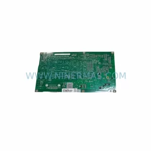
LTi Motion LSC-070-3-30-560-P5B0H2MM0 Retrofit Servo Drive
Verify the part, confirm the platform family, and move straight into quotation with the right commercial details.
RFQ Ready
- SKULSC-070-3-30-560-P5B0H2MM0
- CategoryPLC & Industrial Automation Modules
- BrandLTI Motion
- SupportAvailability, lead time, condition, and shipping coordination
How Buyers Usually Use This Page
- Confirm the exact part number and platform family before sending the quote request.
- Use direct email when quantity, condition, and destination are already defined internally.
- Switch to the broader brand or category archive when you need alternates nearby.
Series Navigation
Move through the most common platform families behind this part.
Product RFQ
Send this part directly for quotation.
Include quantity, required condition, destination country, and target delivery timing. Current reference: LTi Motion LSC-070-3-30-560-P5B0H2MM0 Retrofit Servo Drive with SKU LSC-070-3-30-560-P5B0H2MM0.
LTi Motion LSC-070-3-30-560-P5B0H2MM0 Retrofit Servo Drive: Seamless Upgrade for Legacy Motion Control Systems
The LTi Motion LSC-070-3-30-560-P5B0H2MM0 is a high-performance servo drive module engineered for demanding industrial environments. As a ruggedized unit within the LSC series, it delivers precise torque and velocity control for legacy motion control platforms that are no longer supported by the original manufacturer. For maintenance engineers and system integrators managing aging production lines, this module represents a direct, retrofit-compatible replacement that eliminates the need for full control cabinet redesign. NINERMAS maintains verified stock of the LSC-070-3-30-560-P5B0H2MM0, with each unit pre-tested prior to shipment and covered by a 12-month warranty.
The LSC-070-3-30-560-P5B0H2MM0 is rated for a 70A continuous output current with a 560V DC bus voltage, making it suitable for mid-to-large servo axis applications in machine tools, packaging lines, press systems, and robotic workcells. Its P5B0H2MM0 option code indicates specific encoder interface, communication, and environmental protection configurations that must be verified against the existing axis wiring and controller configuration before installation.
Upgrade Compatibility Table
| Parameter | Legacy Specification | LSC-070-3-30-560-P5B0H2MM0 Specification | Retrofit Notes |
|---|---|---|---|
| Continuous Output Current | Varies by replaced unit | 70 A | Verify motor nameplate current does not exceed drive rating |
| DC Bus Voltage | Typically 540–600 V DC | 560 V DC | Confirm power supply module (e.g. LSC-PSU series) output matches bus voltage |
| Communication Interface | SystemBus / CANopen / SERCOS | Per P5B0H2MM0 option code | Confirm protocol with existing controller; update node address if required |
| Encoder Feedback | Resolver / Incremental / EnDat | Per H2 option (EnDat 2.1/2.2 compatible) | Verify encoder cable pinout; replace encoder cable if connector type differs |
| Mounting / Backplane | LSC rack backplane | Standard LSC backplane slot | Confirm slot width and backplane connector alignment before insertion |
| Terminal Wiring | X1/X2/X3 terminal blocks | Identical terminal layout | Label all wires before removal; photograph existing wiring for reference |
| Installation Space | Standard LSC module width | Same form factor | No cabinet modification required for direct slot replacement |
| Commissioning Tool | LTi Motion DriveManager / EASY | Compatible with DriveManager 5.x | Upload saved axis parameters from previous drive before power-on |
| Warranty | OEM warranty expired (EOL) | 12-Month NINERMAS Warranty | Covers functional failure under normal operating conditions |
Retrofit Planning for Existing Automation Systems
Replacing the LSC-070-3-30-560-P5B0H2MM0 within an existing LSC multi-axis rack requires a structured approach to avoid unplanned downtime and configuration errors. The LSC series is a modular architecture: individual axis modules share a common DC bus supplied by a dedicated power supply module such as the LSC-PSU-3-30-560 or a compatible regenerative supply unit. Before removing the faulty drive, engineers must confirm that the shared bus capacitor bank is fully discharged and that the power supply module is isolated. Failure to do so risks damage to adjacent axis modules and personnel injury.
In a typical multi-axis cabinet, the LSC-070-3-30-560-P5B0H2MM0 operates alongside smaller axis modules such as the LSC-035-3-30-560 for lighter servo axes and the LSC-140-3-30-560 for heavier spindle or gantry axes. The backplane connector on the LSC rack carries both the DC bus rails and the SystemBus communication link. When inserting the replacement module, ensure the backplane connector is fully seated and the module locking mechanism is engaged before applying power.
Communication configuration is a critical step. In systems using the LTi Motion SystemBus protocol, each axis module is assigned a node address via DIP switch or software parameter. After installing the LSC-070-3-30-560-P5B0H2MM0, the node address must match the original assignment recognized by the master controller — typically an LTi Motion CDA or CDB series motion controller, or a third-party PLC with a SystemBus master card. If the system uses CANopen, the COB-ID and baud rate settings must be restored from the saved project file before the controller scan cycle is restarted.
Encoder feedback wiring deserves particular attention. The P5B0H2MM0 option code includes an EnDat-compatible encoder interface. If the existing motor uses a resolver or an older incremental encoder, an encoder signal converter or a different option variant may be required. Always verify the encoder cable shield grounding at both the motor and drive ends to prevent EMI-induced position errors during high-speed operation.
For systems that also require I/O expansion during the retrofit, the LSC series supports digital and analog I/O extension modules mounted in the same rack. Adding an LSC-DIO expansion module allows additional digital inputs and outputs to be mapped to the axis controller without modifying the main PLC program. If the HMI panel — such as an LTi Motion or third-party operator panel connected via RS-232 or Ethernet — displays axis status screens, the screen variable addresses must be verified against the new drive’s parameter map to ensure correct display after replacement.
Programming cable access is required during commissioning. The DriveManager 5.x software connects via USB or RS-232 to the front panel service port of the LSC module. Before first power-on, load the saved axis parameter set (.dmp or .prj file) from the previous drive. Pay particular attention to motor data parameters (rated current, pole pairs, encoder resolution), speed and torque limits, and safety-relevant parameters such as following error thresholds and STO (Safe Torque Off) configuration. After parameter upload, perform a controlled jog test at reduced speed before returning the axis to automatic production mode.
Downtime Control During System Migration
Minimizing unplanned downtime during an LSC-070-3-30-560-P5B0H2MM0 replacement requires preparation before the maintenance window begins. The following steps are recommended to protect program logic, maintain field control continuity, and reduce retrofit risk:
1. Pre-Shutdown Backup: Use DriveManager 5.x to export all axis parameters from the faulty drive while it is still partially functional, or retrieve the last saved backup from the commissioning archive. Document the current node address, encoder type, and communication baud rate settings.
2. Controlled Power-Down Sequence: Disable the axis in software before cutting power. Allow the DC bus to discharge fully (minimum 5 minutes after mains isolation) before touching any backplane connector or terminal block. Use a voltmeter to confirm bus voltage is below 50 V DC before proceeding.
3. Module Swap and Wiring Verification: Insert the replacement LSC-070-3-30-560-P5B0H2MM0 into the same backplane slot. Reconnect all terminal blocks in the original order using the pre-removal photographs as reference. Verify encoder cable shield continuity with a multimeter before closing the cabinet door.
4. Parameter Restore and Commissioning: Power up the system in service mode. Upload the saved parameter set via DriveManager. Confirm node address assignment and communication link status on the master controller. Perform a low-speed jog test on the affected axis before releasing the machine to production. Total replacement time for a prepared team is typically 2–4 hours per axis, including parameter restore and functional test.
5. Post-Commissioning Verification: Run the machine through a complete production cycle at reduced speed. Monitor axis following error, motor temperature, and drive status LEDs for the first 30 minutes of operation. Log the commissioning date and replacement unit serial number in the maintenance record for warranty tracking purposes.
Retrofit Support FAQ
Q1: Is the LSC-070-3-30-560-P5B0H2MM0 a direct drop-in replacement for my existing LSC-070 axis module?
In most cases, yes — provided the option code (P5B0H2MM0) matches the encoder interface, communication protocol, and environmental protection level of the original unit. If your existing module has a different option suffix, contact NINERMAS to confirm compatibility or identify the correct variant for your application.
Q2: Has each unit been tested before shipment?
Yes. Every LSC-070-3-30-560-P5B0H2MM0 supplied by NINERMAS undergoes functional pre-shipment testing, including power-on verification, communication interface check, and encoder feedback validation. A test report is available upon request. All units are covered by a 12-month warranty from the date of shipment.
Q3: What commissioning tools and software are required for installation?
The LTi Motion DriveManager 5.x software (Windows-compatible) is required for parameter upload and axis commissioning. A USB-to-RS-232 adapter or direct RS-232 cable is needed to connect to the drive’s front panel service port. NINERMAS can provide guidance on software version compatibility for your specific controller platform.
Q4: What is the lead time and stock availability?
NINERMAS maintains ready stock of the LSC-070-3-30-560-P5B0H2MM0 to support urgent maintenance and planned retrofit projects. Standard lead time for in-stock units is 3–7 business days for international shipment. For large-quantity or long-term supply agreements, contact our sales team to discuss reserved inventory arrangements and volume pricing.
| Product Series | Other series |
|---|
Catalog Continuation
More LTI Motion modules in the catalog.
Use the brand lane to compare nearby part numbers, platform-adjacent modules, and other inquiry-ready listings before sending your final RFQ.
SKU: SA54.0550.0033.0000.0
LTI SA54-0550-0033-0000-0 Retrofit Servo Drive Legacy Systems
SKU: LSC-130-3-20-560-A5B2R1PM0M
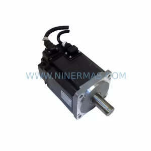
LTI MOTION LSC-130-3-20-560-A5B2R1PM0M Retrofit AC Servo Motor
SKU: LSC-060-3-30-560-P5B0H2MM0
LTI Motion LSC-060-3-30-560-P5B0H2MM0 Safety-Reliable Servo Drive
SKU: LSC-070-2-50-560-P5B0R1PM0
LTI MOTION LSC-070-2-50-560-P5B0R1PM0 Safety-Reliable Servo Drive
Catalog Continuation
Alternative parts within PLC & Industrial Automation Modules.
Stay inside the same system family when you need substitutes, adjacent modules, or a broader shortlist for procurement review.
SKU: 6FC5357-0BB12-0AE0
Siemens 6FC5357-0BB12-0AE0 Service-Ready Industrial Spare Part
SKU: 3BSE011790R1(PXHK401)
ABB 3BSE011790R1 PXHK401 Retrofit-Ready Communication Module