Original Industrial Spare Part
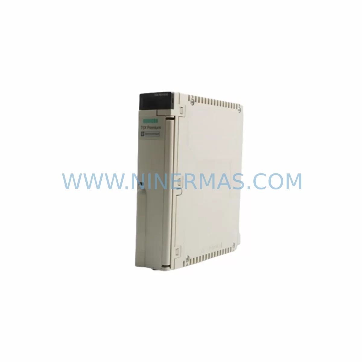
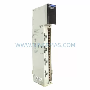
Schneider TSXPSY1610 Retrofit-Compatible Power Supply for Legacy Systems
Verify the part, confirm the platform family, and move straight into quotation with the right commercial details.
RFQ Ready
- SKUTSXPSY1610
- CategoryPLC & Industrial Automation Modules
- BrandSchneider Electric
- SupportAvailability, lead time, condition, and shipping coordination
How Buyers Usually Use This Page
- Confirm the exact part number and platform family before sending the quote request.
- Use direct email when quantity, condition, and destination are already defined internally.
- Switch to the broader brand or category archive when you need alternates nearby.
Series Navigation
Move through the most common platform families behind this part.
Product RFQ
Send this part directly for quotation.
Include quantity, required condition, destination country, and target delivery timing. Current reference: Schneider TSXPSY1610 Retrofit-Compatible Power Supply for Legacy Systems with SKU TSXPSY1610.
Schneider TSXPSY1610 Retrofit-Compatible Power Supply for Legacy Systems
The Schneider Electric TSXPSY1610 is a 24 VDC input power supply module designed for the TSX Series programmable logic controller platform. As legacy TSX Premium and TSX Micro installations continue to operate across manufacturing, utilities, and process industries, the TSXPSY1610 remains a critical retrofit and replacement component for engineers managing aging control infrastructure. This module delivers stable, regulated power to the TSX rack backplane, supporting continued operation of I/O modules, communication processors, and CPU units without requiring a full system overhaul.
For facilities running TSX Premium racks — including the TSXRKY4, TSXRKY6, and TSXRKY8EX extension racks — the TSXPSY1610 provides the 24 VDC bus power required to sustain field-side I/O and internal logic simultaneously. Its compact form factor fits standard TSX rack slots, making it a direct mechanical and electrical replacement for failed or end-of-life power supply units without modification to the existing cabinet layout.
Upgrade Compatibility Table
| Parameter | TSXPSY1610 Specification | Retrofit Notes |
|---|---|---|
| Input Voltage | 24 VDC (18–30 VDC range) | Verify existing cabinet DC bus voltage before installation |
| Output Power | 16 W internal bus | Confirm total I/O module load does not exceed rated output |
| Compatible Racks | TSXRKY4, TSXRKY6, TSXRKY8EX | Slot 0 installation; no address configuration required |
| Communication Compatibility | Unifilar Modbus, Uni-Telway, Fipio | No protocol reconfiguration needed on power supply replacement |
| Mounting | DIN rail / rack slot | Same footprint as predecessor PSY models; no panel modification |
| Replacement Models | TSXPSY1610 replaces TSXPSY1600, TSXPSY2600 | Confirm firmware version on TSXP57 CPU before swapping |
| Commissioning | No software configuration required | Power cycle rack after installation; verify LED status indicators |
| Warranty | 12-Month Warranty | Pre-shipment functional test included | |
Retrofit Planning for Existing Automation Systems
When planning a retrofit around the TSXPSY1610, the scope of work typically extends beyond the power supply itself. Engineers replacing a failed PSY module in an active production line must audit the full rack assembly before ordering. A standard TSX Premium rack may house a TSXP574634M or TSXP576634M CPU module alongside discrete I/O modules such as the TSXDEY16D2 (16-channel 24 VDC digital input) and TSXDSY16T2 (16-channel transistor output). Each of these modules draws from the internal bus powered by the PSY slot, so verifying the aggregate current draw against the 16 W rating of the TSXPSY1610 is a mandatory pre-installation step.
In systems where analog signal conditioning is involved, modules like the TSXAEY414 (4-channel analog input) or TSXASY410 (4-channel analog output) may be present. These modules are sensitive to power interruptions, and any PSY replacement should be coordinated with a controlled shutdown sequence to avoid signal drift or calibration loss. Where Fipio fieldbus communication is active, the TSXFPP10 Fipio processor card installed in the CPU rack must be verified for continuity after the power supply swap — a brief bus interruption during replacement can trigger device re-enumeration on the Fipio segment.
For sites using Uni-Telway or Modbus RTU communication between the TSX Premium CPU and remote HMI panels — such as legacy XBTF024110 or XBTGT2330 Magelis terminals — the communication link should be monitored during and after the PSY replacement. HMI screen variables tied to PLC data blocks may require a forced refresh or communication reset if the CPU enters a fault state during the power transition. Documenting the current HMI variable mapping before the swap reduces commissioning time significantly.
In extension rack configurations using the TSXRKY8EX with a TSXCBY100K inter-rack cable, the extension rack power supply must also be assessed independently. The TSXPSY1610 powers only the rack in which it is installed; extension racks require their own dedicated PSY module. Overlooking this during a multi-rack retrofit is a common source of post-installation faults. Additionally, if the control cabinet includes a TSXSCP114 PCMCIA communication card for programming access, ensure the card is removed before powering down the CPU to avoid potential memory corruption during the transition.
Downtime Control During System Migration
Minimizing unplanned downtime during a TSX power supply replacement requires a structured approach. Before any physical intervention, a full backup of the PLC application program should be extracted using Unity Pro or PL7 Pro software via the programming port or Ethernet connection. This backup preserves the ladder logic, function block diagrams, data tables, and I/O symbol tables that define the machine’s operational behavior. If the CPU is a TSXP574634M running PL7 Pro application code, the backup file should be stored on a local engineering workstation and verified for integrity before proceeding.
The recommended replacement sequence is: notify operations of the planned outage window, execute a controlled PLC stop command, de-energize the 24 VDC supply to the rack, extract the failed TSXPSY1610, insert the replacement module, restore DC power, and observe the CPU restart sequence. The entire physical swap typically takes under 15 minutes for a trained technician. The majority of downtime risk lies in the post-swap verification phase — confirming that all I/O modules have returned to their pre-fault states, that communication links have re-established, and that the HMI is displaying live process data correctly.
For critical processes where even a brief stop is unacceptable, a hot-standby architecture using a redundant TSX Premium CPU configuration may be worth evaluating as a longer-term upgrade path. However, for the majority of legacy installations, a well-prepared cold-swap of the TSXPSY1610 with a pre-tested replacement unit — verified through our pre-shipment functional test protocol — represents the lowest-risk, lowest-cost path to restoring system availability. Our 12-month warranty covers the replacement module from the date of shipment, providing assurance throughout the post-retrofit stabilization period.
Retrofit Support FAQ
Q1: Is the TSXPSY1610 a direct replacement for the TSXPSY1600 and TSXPSY2600?
The TSXPSY1610 is the current production successor to the TSXPSY1600 and is mechanically and electrically compatible with the same TSX rack slots. The TSXPSY2600 is a 26 W variant; if your existing rack load is close to 26 W, verify the aggregate module current draw before substituting with the 16 W TSXPSY1610. In most standard I/O configurations, the TSXPSY1610 is a suitable drop-in replacement.
Q2: Does replacing the power supply require any changes to the PLC program or I/O addressing?
No. The TSXPSY1610 occupies slot 0 of the TSX rack and does not carry a configurable module address. Replacing the power supply does not alter the I/O module addresses, CPU configuration, or application program. After installation, a normal power-on sequence will restore the system to its previous operating state, provided the CPU memory has not been cleared.
Q3: What pre-shipment testing is performed on the TSXPSY1610 before delivery?
Each TSXPSY1610 unit undergoes a functional power-on test prior to shipment, verifying output voltage regulation, internal bus stability, and LED indicator behavior under load. Units that do not meet specification are quarantined and not shipped. A test record is available upon request. All units are covered by a 12-month warranty from the date of shipment.
Q4: What is the typical lead time and stock availability?
We maintain stock of the TSXPSY1610 to support urgent retrofit and breakdown replacement scenarios. Standard orders are processed and dispatched within 1–3 business days. For large-quantity orders or scheduled maintenance programs requiring multiple units, please contact our sales team at sale@ninermas.com or call +0086 187 5021 5667 to confirm availability and arrange priority fulfillment.
| Product Series | TSX |
|---|---|
| Country of Origin | FR |
Catalog Continuation
More Schneider Electric modules in the catalog.
Use the brand lane to compare nearby part numbers, platform-adjacent modules, and other inquiry-ready listings before sending your final RFQ.
Catalog Continuation
Alternative parts within PLC & Industrial Automation Modules.
Stay inside the same system family when you need substitutes, adjacent modules, or a broader shortlist for procurement review.