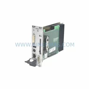
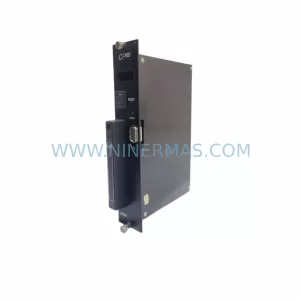
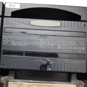
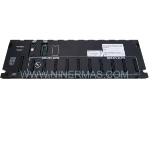
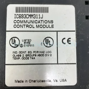
Original Industrial Spare Part
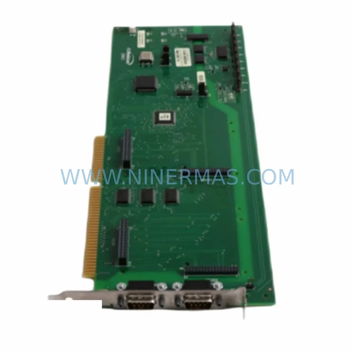
ROBICON A1A363818.00M Retrofit-Compatible Drive Module for Legacy Systems
Verify the part, confirm the platform family, and move straight into quotation with the right commercial details.
RFQ Ready
- SKUA1A363818.00M
- CategoryPLC & Industrial Automation Modules
- BrandRobicon
- SupportAvailability, lead time, condition, and shipping coordination
How Buyers Usually Use This Page
- Confirm the exact part number and platform family before sending the quote request.
- Use direct email when quantity, condition, and destination are already defined internally.
- Switch to the broader brand or category archive when you need alternates nearby.
Series Navigation
Move through the most common platform families behind this part.
Product RFQ
Send this part directly for quotation.
Include quantity, required condition, destination country, and target delivery timing. Current reference: ROBICON A1A363818.00M Retrofit-Compatible Drive Module for Legacy Systems with SKU A1A363818.00M.
ROBICON A1A363818.00M Retrofit-Compatible Drive Module for Legacy Systems
The ROBICON A1A363818.00M is a critical drive module within the Perfect Harmony medium-voltage AC drive platform, widely deployed across petrochemical, power generation, cement, mining, and heavy industrial facilities. As original equipment manufacturers phase out legacy drive components and reduce spare parts availability, the A1A363818.00M has become one of the most sought-after retrofit and replacement modules for engineers tasked with extending the operational life of existing Perfect Harmony drive cabinets without committing to a full system overhaul.
This module is designed to slot into existing Perfect Harmony drive enclosures, maintaining compatibility with the original power cell architecture, control backplane, and fiber-optic communication links that are characteristic of the Perfect Harmony topology. For maintenance engineers and procurement specialists managing aging drive infrastructure, sourcing a verified, pre-tested A1A363818.00M represents the most cost-effective path to restoring full drive functionality while avoiding the capital expenditure and extended downtime associated with a complete drive replacement.
Upgrade Compatibility Table
| Parameter | Details |
|---|---|
| Part Number | A1A363818.00M |
| Brand / OEM | ROBICON (Siemens Perfect Harmony platform) |
| Drive Series | Perfect Harmony Medium Voltage AC Drive |
| Module Function | Drive power cell / control module (retrofit-compatible) |
| Installation Interface | Compatible with existing Perfect Harmony cell bay and backplane connectors |
| Communication Link | Fiber-optic cell communication bus (standard Perfect Harmony topology) |
| Replacement Scope | Direct drop-in for failed or degraded A1A363818.00M units in legacy cabinets |
| Power Supply Compatibility | Verify input voltage rating and cell transformer tap before installation |
| Commissioning Requirement | Cell address configuration via drive controller; no firmware re-flash typically required |
| Pre-Shipment Testing | Full functional test performed prior to dispatch |
| Warranty | 12-Month Warranty included |
| Stock Status | Available — long-term supply program supported |
Retrofit Planning for Existing Automation Systems
Replacing the A1A363818.00M within an operational Perfect Harmony drive system requires a structured approach that accounts for the interdependencies between the power cell modules, the cell bypass contactors, the master drive controller, and the isolation transformer. Before any physical swap is initiated, the engineering team should confirm the exact cell position within the drive cabinet — Perfect Harmony systems use a cascaded H-bridge topology where each power cell occupies a defined slot, and the cell address must be correctly assigned in the drive controller after module replacement.
Power supply verification is a non-negotiable first step. The input voltage to each cell is derived from a dedicated winding on the phase-shifting isolation transformer — commonly a 12-pulse, 18-pulse, or 24-pulse transformer depending on the drive rating. Confirming that the transformer secondary voltage matches the input rating of the replacement A1A363818.00M prevents immediate damage upon energization. Similarly, the DC bus capacitor bank within the replacement module should be inspected and, if the module has been in storage for an extended period, a controlled pre-charge sequence should be performed before full voltage is applied.
Terminal wiring on the cell input and output sides must be verified against the original cabinet drawings. Perfect Harmony cells use standardized bus bar connections, but torque specifications and insulation clearances must be respected, particularly in medium-voltage environments where creepage distances are critical for safety compliance. The fiber-optic communication cables connecting each cell to the Perfect Harmony NXG or GH180 drive controller must be re-seated and inspected for bend radius violations that could cause intermittent communication faults.
For sites running the Perfect Harmony with a Siemens SIMATIC S7-300 or S7-400 PLC for process coordination, the PLC program logic referencing drive status words, fault codes, and speed references should be reviewed to confirm that the replacement module does not introduce any change in the drive’s communication register map. In most cases, a like-for-like A1A363818.00M replacement preserves full PLC compatibility without requiring program modifications. However, if the site has previously upgraded the drive controller firmware, a compatibility check between the new cell module firmware version and the controller version is advisable.
HMI screens connected via Profibus DP or Modbus RTU to the Perfect Harmony controller should be tested after module replacement to confirm that all drive status displays, fault history pages, and speed reference inputs respond correctly. Sites using a Siemens OP277 or TP900 operator panel should verify that the panel project version matches the current controller configuration. Where the drive is integrated into a DCS environment — such as a Honeywell Experion PKS, ABB System 800xA, or Yokogawa CENTUM VP — the DCS tag assignments for drive run/stop commands, speed feedback, and fault relay outputs should be confirmed as part of the post-replacement commissioning checklist.
I/O expansion modules connected to the drive’s auxiliary I/O board, including digital input modules for remote start/stop interlocks and analog output modules for speed feedback to the control room, should be tested under simulated process conditions before returning the drive to service. Where the drive cabinet includes a bypass contactor assembly for emergency motor operation, the bypass logic should be tested independently to confirm that the replacement cell module does not interfere with the bypass transfer sequence.
Downtime Control During System Migration
Minimizing unplanned downtime during a Perfect Harmony drive module replacement is achievable through disciplined pre-staging and a clearly defined switching sequence. The most effective approach is to pre-configure the replacement A1A363818.00M off-line — verifying the cell address setting, inspecting the fiber-optic connectors, and confirming the DC bus pre-charge behavior — before the production line is taken offline. This preparation reduces the active maintenance window to the physical swap, wiring verification, and functional test sequence, which experienced drive technicians can typically complete within two to four hours for a single cell replacement.
Where the Perfect Harmony drive supports cell bypass operation, it may be possible to temporarily bypass the faulted cell and continue motor operation at a derated output voltage while the replacement module is sourced and staged. This approach is particularly valuable in continuous process industries where even a brief production interruption carries significant financial consequences. The drive controller’s cell bypass feature should be confirmed as active and correctly configured before relying on this capability.
Original program logic stored in the Perfect Harmony NXG controller is retained in non-volatile memory and is not affected by a power cell replacement. However, a full parameter backup should be performed before any maintenance activity using the drive’s parameter upload function or a compatible programming tool. This backup protects against accidental parameter loss during the maintenance sequence and provides a reference for post-replacement commissioning verification.
Post-replacement, the drive should be energized in a controlled sequence: first applying control power to verify communication with all cells, then applying main power with the motor disconnected to confirm cell voltage balance, and finally performing a no-load run before reconnecting the motor and returning to process control. This staged energization sequence catches wiring errors and cell communication faults before they can cause motor damage or process upsets.
Retrofit Support FAQ
Q1: Is the A1A363818.00M a direct drop-in replacement for the original module in my Perfect Harmony cabinet?
Yes. The A1A363818.00M is designed as a direct replacement for the corresponding cell position in the Perfect Harmony drive series. Physical dimensions, bus bar connection points, and fiber-optic communication interfaces are consistent with the original cabinet design. Cell address configuration is performed via the drive controller after installation and does not require hardware modification.
Q2: What commissioning steps are required after installing the replacement module?
After physical installation, the technician should confirm the cell address assignment in the Perfect Harmony NXG or GH180 controller, verify fiber-optic communication link status for the new cell, perform a DC bus pre-charge check, and conduct a no-load motor run before returning to full process operation. A complete parameter comparison against the pre-maintenance backup is also recommended.
Q3: Has the A1A363818.00M been tested before shipment?
Yes. Every A1A363818.00M unit dispatched by NINERMAS undergoes a full functional test prior to shipment. Test records are available upon request. All units are covered by a 12-month warranty from the date of shipment, covering manufacturing defects and functional failures under normal operating conditions.
Q4: Can you support long-term spare parts supply for our Perfect Harmony drive fleet?
Yes. NINERMAS maintains a long-term supply program for Perfect Harmony drive components, including power cell modules, control boards, fiber-optic communication assemblies, and associated spare parts. For sites managing multiple Perfect Harmony drives or planning a phased retrofit program, we can discuss stock commitment arrangements and extended supply agreements to support your maintenance planning horizon.
| Product Series | Legacy |
|---|
Catalog Continuation
More Robicon modules in the catalog.
Use the brand lane to compare nearby part numbers, platform-adjacent modules, and other inquiry-ready listings before sending your final RFQ.
Catalog Continuation
Alternative parts within PLC & Industrial Automation Modules.
Stay inside the same system family when you need substitutes, adjacent modules, or a broader shortlist for procurement review.