Original Industrial Spare Part
Schneider PN072139P904 Service-Ready Spare Part for Industrial Maintenance
Verify the part, confirm the platform family, and move straight into quotation with the right commercial details.
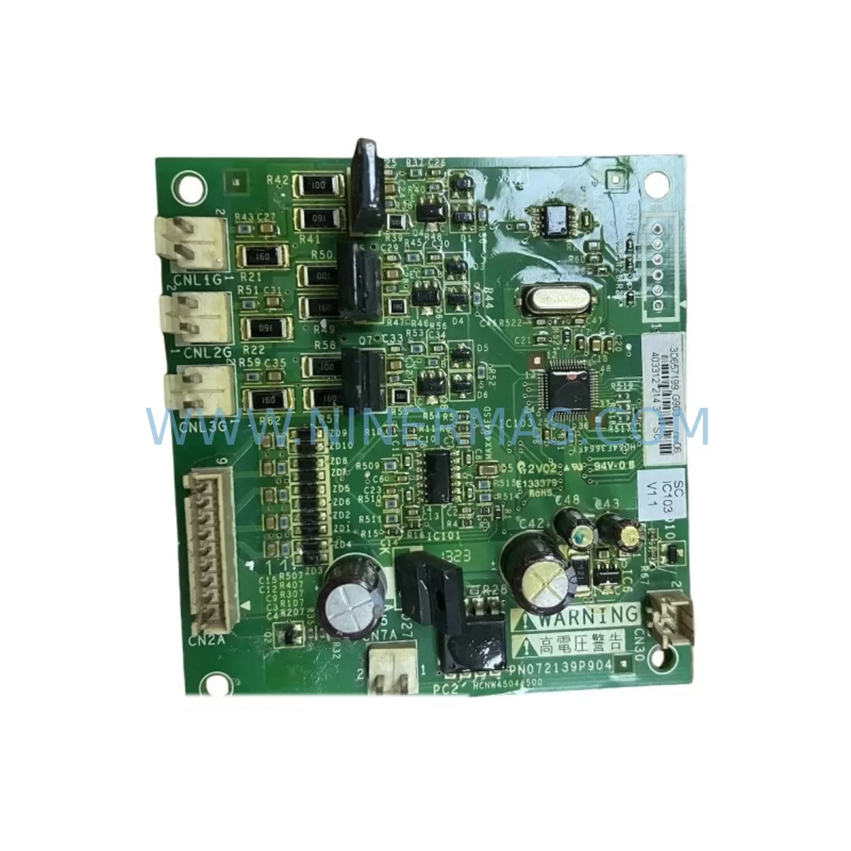
RFQ Ready
- SKUPN072139P904
- CategoryPLC & Industrial Automation Modules
- BrandSchneider
- SupportAvailability, lead time, condition, and shipping coordination
How Buyers Usually Use This Page
- Confirm the exact part number and platform family before sending the quote request.
- Use direct email when quantity, condition, and destination are already defined internally.
- Switch to the broader brand or category archive when you need alternates nearby.
Series Navigation
Move through the most common platform families behind this part.
Product RFQ
Send this part directly for quotation.
Include quantity, required condition, destination country, and target delivery timing. Current reference: Schneider PN072139P904 Service-Ready Spare Part for Industrial Maintenance with SKU PN072139P904.
Schneider PN072139P904 Service-Ready Spare Part for Industrial Maintenance
The Schneider PN072139P904 is a ruggedized inverter power module engineered for demanding industrial environments. As a service-ready original spare part, it is designed to deliver immediate drop-in replacement capability for Altivar series variable frequency drives deployed across manufacturing lines, process automation systems, and heavy-duty control cabinets. For maintenance engineers managing aging automation infrastructure, sourcing a verified PN072139P904 replacement is critical to minimizing unplanned downtime and restoring drive functionality with full electrical compatibility.
Industrial facilities operating Schneider Altivar drives — including the Altivar 71, Altivar 61, and related Altivar Process series — depend on the power module stage as the core energy conversion component. When this module fails, the entire drive becomes non-functional, halting conveyor systems, pump stations, compressor banks, and HVAC control loops. Stocking the PN072139P904 as a critical spare ensures that maintenance teams can execute rapid field replacement without waiting for extended lead times from standard distribution channels.
Spare Maintenance Table
| Parameter | Specification |
|---|---|
| Part Number | PN072139P904 |
| Brand | Schneider Electric |
| Series | Altivar (ATV71 / ATV61 / Altivar Process) |
| Product Type | Ruggedized Inverter Power Module |
| Application | Variable Frequency Drive (VFD) Power Stage Replacement |
| Operating Environment | Harsh Industrial — High Vibration, Dust, Humidity Rated |
| Voltage Compatibility | 3-Phase AC Input, Drive-Rated DC Bus Voltage |
| Mounting | Direct module replacement — OEM form factor |
| Origin | France (Schneider Electric Manufacturing) |
| Compatibility Verification | Cross-referenced against Altivar drive serial and catalog number |
| Condition | New, Original Spare — Pre-shipment tested |
| Warranty | 12 Months from date of shipment |
| Lead Time | In-stock — ships within 2 business days |
| Maintenance Recommendation | Replace alongside DC bus capacitors and gate driver board during major overhaul |
Maintenance Planning for Continuous Operation
When a maintenance or procurement engineer schedules replacement of the PN072139P904 power module, best practice dictates a comprehensive inspection of all interdependent components within the same drive cabinet and electrical circuit. Failing to address adjacent wear items during the same maintenance window is a leading cause of repeat failures and secondary downtime events.
Begin with the DC bus capacitor bank — electrolytic capacitors in Altivar drives have a defined service life and should be replaced concurrently with any power module swap, particularly in drives that have exceeded five years of continuous operation. Next, inspect the gate driver board (also referred to as the IGBT trigger card), which interfaces directly with the PN072139P904 and is subject to thermal stress from repeated switching cycles. A degraded gate driver can cause premature failure of a newly installed power module.
The control board and its associated I/O expansion cards should be checked for corrosion on connector pins and verified for firmware compatibility with the replacement module. In multi-drive installations, the communication module — whether Modbus RTU, CANopen, Profibus DP, or Ethernet/IP — must be reseated and tested to confirm fieldbus integrity after the power module replacement. Loss of communication after a drive repair is a common commissioning error that delays line restart.
Inspect the braking resistor and braking chopper circuit if the drive application involves regenerative loads such as hoists, centrifuges, or downhill conveyors. These components absorb excess energy during deceleration and are frequently overlooked during reactive maintenance. Similarly, the input line reactor or EMC filter module upstream of the drive should be checked for continuity and insulation resistance, as harmonic distortion from a failing power stage can damage these passive components over time.
For cabinet-level maintenance, verify the condition of the 24VDC control power supply feeding the drive’s logic circuits, as well as any safety relay modules or STO (Safe Torque Off) wiring connected to the drive’s safety inputs. Terminal blocks and DIN rail-mounted terminal strips should be inspected for loose connections and signs of thermal discoloration. Finally, if the installation includes a keypad or remote HMI panel (such as the Schneider Magelis or Altivar Graphic Display Terminal), confirm that the display communication link is intact and that parameter sets are backed up before powering down the drive for module replacement.
Site Replacement Workflow
Step 1 — Isolation and Lockout/Tagout: De-energize the drive and apply LOTO procedures. Allow a minimum of 10 minutes for DC bus capacitors to discharge before opening the drive enclosure. Verify bus voltage with a calibrated multimeter before touching internal components.
Step 2 — Documentation and Parameter Backup: Record all drive parameters using the keypad, PC software (SoMove), or a parameter backup card if available. Photograph wiring connections and label all cables before disconnection. This step is critical for restoring the drive to its pre-failure configuration after the PN072139P904 module is installed.
Step 3 — Module Removal: Disconnect the DC bus busbars, gate driver ribbon cable, and any thermal sensor connectors attached to the existing power module. Remove the module mounting hardware and extract the unit carefully to avoid damaging adjacent components. Note the orientation and seating depth for reference during installation.
Step 4 — Compatibility Verification: Before installing the replacement PN072139P904, cross-reference the drive’s catalog number and serial number against Schneider Electric’s compatibility matrix. Confirm that the replacement module’s voltage and current ratings match the original specification. Inspect the new module for any shipping damage and verify that all connector interfaces are clean and undamaged.
Step 5 — Installation and Torque: Seat the PN072139P904 into the drive chassis, reconnect all busbars and signal cables, and torque all fasteners to the manufacturer’s specified values. Incorrect torque on busbar connections is a primary cause of contact resistance failures and localized overheating.
Step 6 — Power-Up and Commissioning: Restore power and perform a no-load test before reconnecting the motor. Verify that the drive displays no fault codes, that output voltage is balanced across all three phases, and that communication with the PLC or DCS is re-established. Restore parameters from backup and conduct a controlled ramp-up test under load before returning the drive to full production service.
This structured replacement workflow reduces average repair time, eliminates rework caused by missed steps, and ensures that the replacement PN072139P904 module operates within its rated parameters from the first power-up.
Spare Parts Support FAQ
Q1: Is the PN072139P904 compatible with all Altivar drive variants?
The PN072139P904 is designed for specific Altivar series drives. Compatibility must be verified against the drive’s full catalog number and power rating before ordering. Our technical team can cross-reference your drive’s nameplate data to confirm fitment. Supplying the drive serial number and catalog number at the time of inquiry eliminates compatibility risk and prevents costly returns.
Q2: What pre-shipment testing is performed on the PN072139P904?
Each unit undergoes electrical continuity verification, insulation resistance testing, and visual inspection for component integrity before dispatch. Units are packed in anti-static, shock-resistant packaging to prevent transit damage. A test report is available upon request for quality-critical procurement processes.
Q3: Can you support long-term or blanket purchase orders for the PN072139P904?
Yes. We support scheduled delivery agreements, consignment stock arrangements, and annual maintenance contract supply for the PN072139P904 and related Altivar spare parts. Long-term supply agreements provide price stability and guaranteed availability, which is particularly valuable for facilities managing fleets of Altivar drives across multiple production lines.
Q4: What does the 12-month warranty cover?
The 12-month warranty covers manufacturing defects and component failures under normal operating conditions from the date of shipment. It does not cover damage resulting from incorrect installation, overvoltage events, or operation outside the module’s rated parameters. Warranty claims are processed with priority turnaround to minimize the impact on production schedules.
| Product Series | Altivar |
|---|---|
| Country of Origin | FR |
Catalog Continuation
More Schneider modules in the catalog.
Use the brand lane to compare nearby part numbers, platform-adjacent modules, and other inquiry-ready listings before sending your final RFQ.
SKU: EOCR-SSD 05 EOCRSSD-05DF7
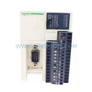
Schneider EOCR-SSD 05 Safety-Reliable Motor Relay for Critical Control
Catalog Continuation
Alternative parts within PLC & Industrial Automation Modules.
Stay inside the same system family when you need substitutes, adjacent modules, or a broader shortlist for procurement review.
SKU: 6SL3224-0BE33-7UA0
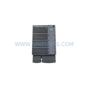
Siemens 6SL3224-0BE33-7UA0 Service-Ready Spare Part
SKU: HENF331395R0001 P4LDA
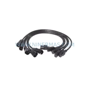
ABB HENF331395R0001 Service-Ready Industrial Spare Part